
Magnetic resonance imaging apparatus and magnetic resonance imaging method

a magnetic resonance imaging and apparatus technology, applied in the field of magnetic resonance imaging apparatus, can solve the problems of difficult high speed computation, less practicality, and complex artifacts produced when the data is roughly obtained by parallel mri, so as to prevent the occurrence of reconstruction artifacts, reduce the number of measurements, and reduce the effect of sparse data sampling specifi

Active Publication Date: 2010-02-18
FUJIFILM HEALTHCARE CORP
View PDF4 Cites 22 Cited by
  • Summary
  • Abstract
  • Description
  • Claims
  • Application Information

AI Technical Summary

Benefits of technology

[0016]In the usual non-Cartesian data sampling epitomized by radial sampling, data sampling in the outermost part of the k-space tends to be sparse in a radial direction. In order to prevent the occurrence of reconstruction artifacts, therefore, the number of radial scanning lines needs to be at least approximately 0.6 times more (256×1.6≈404) than the number of Fourier transform points (for example, 256×256). If the number of radial scanning lines is less than the number (404), radial artifacts may appear. When the parallel MRI is applied to the non-Cartesian data sampling with a purpose to reduce the number of measurements, a generalized SEMSE method as described in Non-patent Document 1 needs to be applied to remove such radial artifacts.
[0017]In the present invention, the artifacts appearing due to sparse data sampling specific to the non-Cartesian imaging is prevented by narrowing the field of view in the reconstruction on the orthogonal coordinate when the non-Cartesian data is converted to the orthogonal data by gridding. The aliasing of image, which may be contained in the orthogonal data due to a narrowed field of view, is removed by the parallel MRI operation in the conventional Cartesian imaging.

Problems solved by technology

In non-Cartesian imaging, the artifacts produced when the data is roughly obtained by applying parallel MRI are more complicated than those produced in Cartesian imaging.
Consequently, the generalized parallel method has disadvantages such as difficulty in high speed computation and lower practicality as it needs to compute a larger amount of computation, including recursive processing.

Method used


Image

  • Magnetic resonance imaging apparatus and magnetic resonance imaging method
  • Magnetic resonance imaging apparatus and magnetic resonance imaging method
  • Magnetic resonance imaging apparatus and magnetic resonance imaging method

Examples


first embodiment

[0024]The imaging sequence equipped in the MRI apparatus will be explained first. According to the present embodiment a radial scan is applied as a pulse sequence of non-Cartesian imaging. FIG. 3 shows a typical 2D radial scan gradient echo (GrE) sequence, as an example of imaging sequence. In this imaging sequence, an RF pulse 501, which is to excite nuclear spins comprising the tissue of a subject (normally, proton), is applied together with a slice encoding gradient magnetic field pulse 502, and then pre-pulses 504 and 506 and the gradient magnetic field pulses 505 and 507 are applied in a direction of two axes (directions G1 and G2). Then, the measurement is performed on the gradient echo signal 508, which reaches peak when the absolute value of the applied amount of pre-pulses becomes equals to that of the gradient magnetic field pulse. Time from the excitation till the generation of echo signals, namely echo time TE is a parameter to determine image contrast and can be set arb...

second embodiment

[0062]The procedure for image re-construction according to the second embodiment is equal to the procedure according to the first embodiment shown in FIG. 1. Namely, non-orthogonal data is sampled by radial scan in Step 101, the non-orthogonal data is gridded on the Cartesian coordinate having a narrower field of view than that of a final view in step 102, Fourier transform is performed in step 103 and the operation for removing aliasing is performed on the data in the real space by using a sensitivity distribution of each element coil in step 107. The coil sensitivity distribution is calculated from the non-orthogonal data at the steps 104-106.

[0063]However, according to the present embodiment, when non-orthogonal data is measured by thinning spokes, the thinning is carried out not at even rate but at uneven rate or with the thinning rate in a direction higher than in other direction. An example of non-Cartesian sampling according to the present embodiment is shown in FIG. 10. (a) ...

third embodiment

[0073]This embodiment is different from the first and second embodiments in the point that non-orthogonal data is sampled using spiral scan but not radial scan. FIG. 11 (a) illustrates how the non-orthogonal data is measured by spiral scan, while FIG. 11 (b) and (c) illustrate the way of gridding of non-orthogonal data. FIG. 11 (d) shows non-orthogonal data measured by conventional spiral scan. It shows an example of single shot spiral, in which all data in the k-space are measured by repeating inversion of the gradient magnetic field after one excitation.

[0074]The spiral scan performs a pulse sequence to measure echo signals for every cycle of sign curve by continuously applying gradient magnetic field as a sign curve with changing (increasing) amplitudes in two axial directions (phase encoding direction and read-out direction). This makes the trajectory in the k-space expand spirally outside the k-space from the origin of the k-space, as shown in FIG. 11 (d). Here, the pitch of sp...


PUM


Abstract

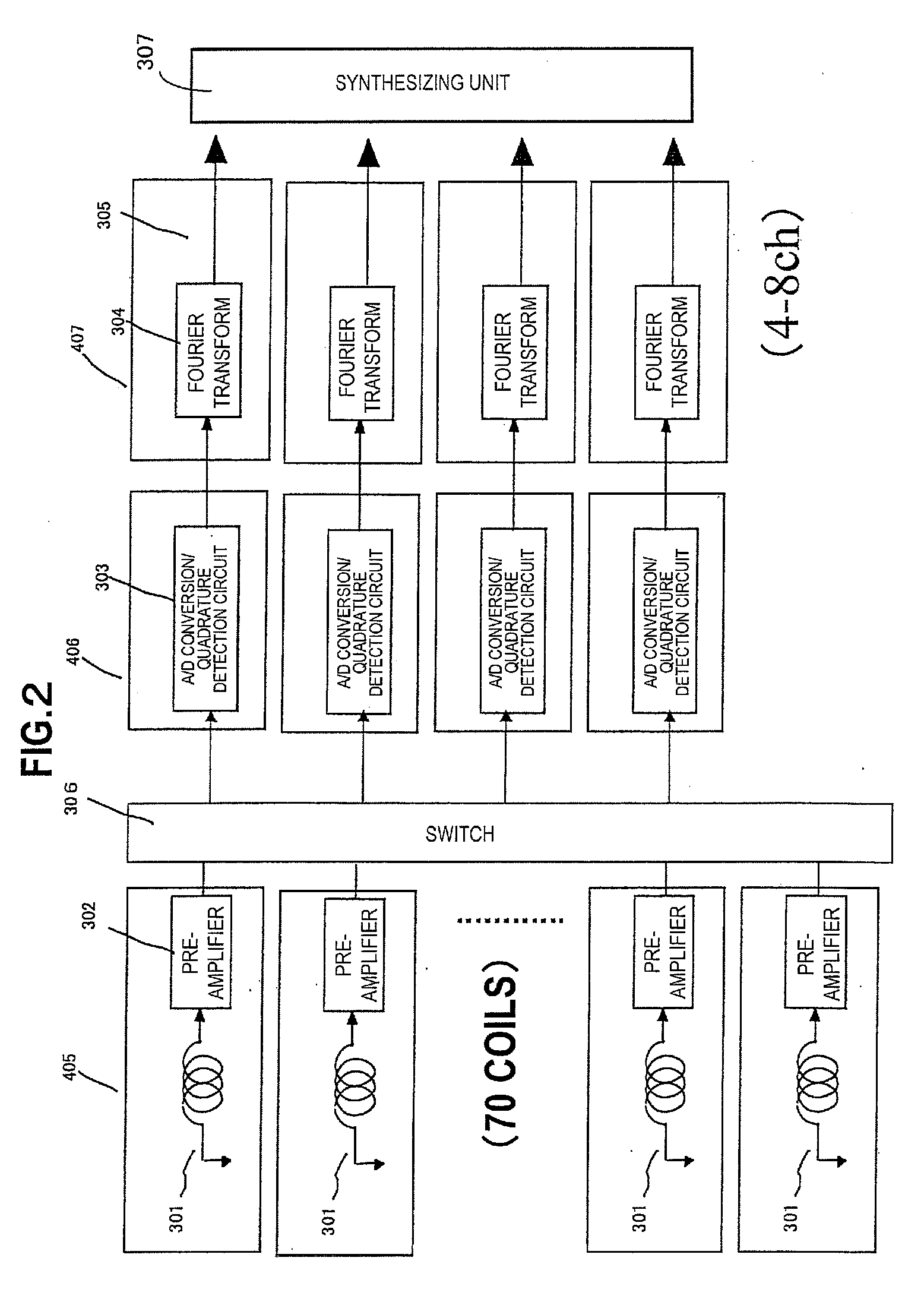
An MRI apparatus capable of performing a high-speed operation for removing aliasing from the data measured by non-Cartesian imaging in a real space with a small amount of operation is provided. Non-Cartesian data sampling is performed by thinning the number of data by using multiple receiver coils having different sensitivity distribution from each other. Image reconstruction means creates orthogonal data by gridding non-orthogonal data obtained by each receiver coil on a grid having an equal spatial resolution to and a narrower field of view than a target image, subjects it to Fourier transform and creates the first image data containing aliasing components. The second image data is created by using the first image data created for each receiver coil and a sensitivity distribution of each receiver coil.

Description

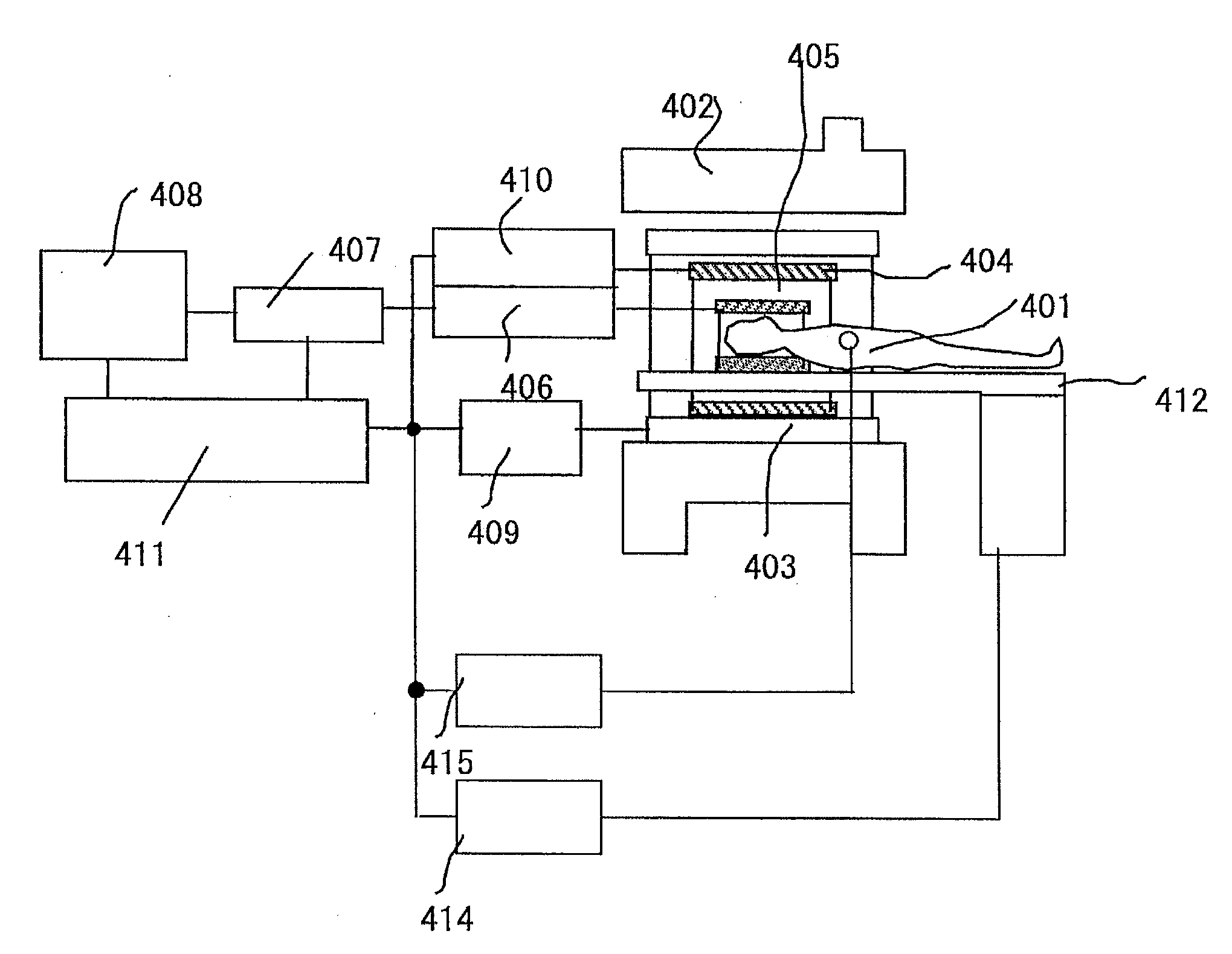
FIELD OF THE INVENTION[0001]The present invention relates to a magnetic resonance imaging (MRI) apparatus that continuously measures nuclear magnetic resonance (hereinafter, referred to as “NMR”) signals from hydrogen, phosphorus and others in a subject and visualizes the distribution of nuclear density, distribution of relaxation time and so forth. More particularly, it relates to a parallel MRI that obtains an image with a wide field of view and without aliasing by means of operation using signals received by a multiple coil composed of multiple receiver coils.PRIOR ART[0002]Recently, in NMR, high-sensitive coils composed of multiple relatively high sensitive element RF coils that are called multiple or phased array coil (hereinafter, referred to as multiple coil) are in heavy usage as an RF coil receiving NMR signals. They can have a larger field of view (FOV) while keeping high sensitivity of element RF coil, and achieve higher sensitivity by synthesizing signals received by eac...

Claims


Application Information

Patent Timeline
IPC IPC(8): G01R33/48G06K9/00
CPCG01R33/4824G01R33/5615G01R33/5611
Inventor TAKAHASHI, TETSUHIKOTAKIZAWA, MASAHIROKAMADA, YASUHIRO
Owner FUJIFILM HEALTHCARE CORP
Learn More