Negative vertical deflection piezoelectric MEMS actuators and method of fabrication

a vertical deflection, piezoelectric technology, applied in the direction of piezoelectric/electrostrictive transducers, generators/motors, transducer types, etc., can solve the problems of large operating voltages providing positive out-of-plane deflections and inability to achieve large negative out-of-plane deflections, and achieve optimal actuator performance

Inactive Publication Date: 2010-02-25
UNITED STATES OF AMERICA THE AS REPRESENTED BY THE SEC OF THE ARMY
View PDF3 Cites 8 Cited by
  • Summary
  • Abstract
  • Description
  • Claims
  • Application Information

AI Technical Summary

Benefits of technology

[0008]where Mact represents the piezoelectric actuation moment, d31 is the high electric field effective piezoelectric coefficient, V is the applied voltage, Ep is the elastic modulus of the piezoelectric, w is the beam width, ybar represents the distance between the x-y neutral axis and an arbitrary reference axis, Ai represents elasticity weighted layer cross sectional areas corresponding to the “transformed section method”, yi represents the distance between individual layer centroids and the arbitrary reference axis, Atot represents cross-sectional areas of all the layers in the piezoelectric MEMS actuator, HPmid represents the distance between the mid-plane of the piezoelectric layer and the arbitrary reference axis. The difference between HPmid and ybar is the value of the piezoelectric moment arm. With the value of the piezoelectric actuation moment, the actuator layer thicknesses and other geometries, and additional mechanics equations for force and displacement for vario

Problems solved by technology

If the opposite polarity voltage is applied, the actuator will bend upward (out of the wafer plane) for all voltages, Consequently, conventional vertical piezoelectric MEMS unimorph actuators

Method used


Image

  • Negative vertical deflection piezoelectric MEMS actuators and method of fabrication
  • Negative vertical deflection piezoelectric MEMS actuators and method of fabrication
  • Negative vertical deflection piezoelectric MEMS actuators and method of fabrication

Examples


Embodiment Construction

[0021]The embodiments herein and the various features and advantageous details thereof are explained more fully with reference to the non-limiting embodiments that are illustrated in the accompanying drawings and detailed in the following description. Descriptions of well-known components and processing techniques are omitted so as to not unnecessarily obscure the embodiments herein. The examples used herein are intended merely to facilitate an understanding of ways in which the embodiments herein may be practiced and to further enable those of skill in the art to practice the embodiments herein. Accordingly, the examples should not be construed as limiting the scope of the embodiments herein.

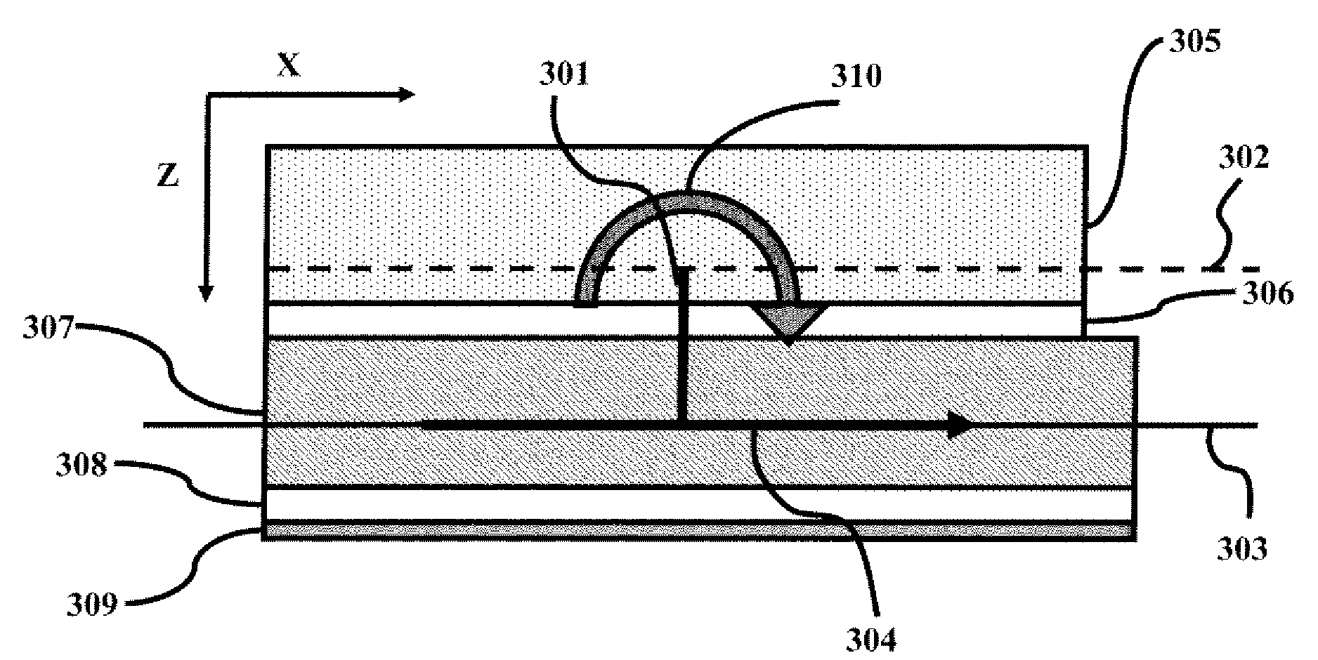
[0022]The embodiments herein provide a piezoelectric MEMS actuator that can achieve large negative deflections by manipulating the location of the neutral axis of the structure with respect to the mid-plane of the piezoelectric thin film and provides a combination of a large negative displaceme...


PUM

PropertyMeasurementUnit
Lengthaaaaaaaaaa
Thicknessaaaaaaaaaa
Forceaaaaaaaaaa

Abstract

Co-fabricating of vertical piezoelectric MEMS actuators that achieve large positive and negative displacements through operating electric fields in excess of the coercive field includes forming a large negative displacement vertical piezoelectric MEMS actuator, forming a bottom structural dielectric layer above a substrate layer; forming a bottom electrode layer above the structural dielectric layer; forming an active piezoelectric layer above the bottom electrode layer; forming a top electrode layer above the active piezoelectric layer; forming a top structural layer above the top electrode layer, wherein the x-y neutral plane of the negative displacement vertical piezoelectric MEMS actuator is above the mid-plane of the active piezoelectric layer, wherein the negative displacement vertical piezoelectric MEMS actuator is partially released from the substrate to allow free motion of the actuator; and combining the large negative displacement vertical piezoelectric MEMS actuator and a large positive displacement vertical piezoelectric MEMS actuator on the same the substrate.

Description

BACKGROUND[0001]1. Technical Field[0002]The embodiments herein generally relate to microelectromechanical systems (MEMS) actuators, and, more particularly to piezoelectric MEMS actuators.[0003]2. Description of the Related Art[0004]MEMS piezoelectric actuators are the basic building blocks for complex electromechanical systems such as radio frequency (RE) MEMS, optical switching, robotics, and many more systems. Typically, piezoelectric actuators outperform electrostatic actuators as they have lower power consumption, smaller size, smaller actuation voltages, and tend to attain greater displacements.[0005]In most conventional piezoelectric actuators, as shown in FIGS. 1(A) and 1(B), the structure includes a structural dielectric layer 104 on top of which the bottom electrode 103 is present. The piezoelectric layer 102 is on top of this bottom electrode 103 and is generally made of lead-zirconate-titanate (PZT), zinc oxide (ZnO), or aluminum nitride (ALN). A top electrode 101 is posi...

Claims


Application Information

Patent Timeline
IPC IPC(8): H01L41/22H02N2/04
CPCH01L41/094H01L41/29Y10T29/42H01L41/332H01L41/318H10N30/2042H10N30/06H10N30/078H10N30/082
Inventor PULSKAMP, JEFFREY SPENCERPOLCAWICH, RONALD G.
Owner UNITED STATES OF AMERICA THE AS REPRESENTED BY THE SEC OF THE ARMY
Why Eureka
Try Eureka