Inverter device

a technology of inverter and inverter, which is applied in the direction of motor/generator/converter stopper, dynamo-electric converter control, motor/generator/converter stopper, etc., can solve the problems of inability to drive single-phase induction motors with high efficiency, and the limit of disseminating permanent magnet motors to the world, etc., to achieve maximum efficiency

Inactive Publication Date: 2010-03-04
KK TOSHIBA
View PDF1 Cites 20 Cited by
  • Summary
  • Abstract
  • Description
  • Claims
  • Application Information

AI Technical Summary

Benefits of technology

[0008]Therefore, an object of the present invention is to provide an inverter device which can drive low-cost induction motors that have widely been used in the world.
[0010]According to the above-described inverter device, individual voltages are supplied to the main and auxiliary windings of the induction motor, whereby optimum currents can be supplied to the main and auxiliary windings. Consequently, the induction motor can be driven with maximum efficiency. Furthermore, since the frequency is automatically reduced by the vector control during starting or overload condition, the induction motor can continuously be rotated without interruption or stop.

Problems solved by technology

However, the permanent magnet motors are expensive so that disseminating the permanent magnet motors to the world has a certain limit.
In view of importance of recent energy saving, it has been a technical problem how the single-phase induction motors could be driven with high efficiency.
However, the induction motor cannot be driven with high efficiency even when the 90-degree phase shifted sinusoidal voltages are supplied to the main and auxiliary windings, as disclosed by JP-A-H02-111288.
Furthermore, although JP-A-S64-8896 discloses a sensorless vector control for a balanced three-phase induction motor, the disclosed control manner cannot in situ be applied to a two-phase induction motor comprising main and auxiliary windings having different winding specifications.

Method used


Image

  • Inverter device
  • Inverter device
  • Inverter device

Examples


second embodiment

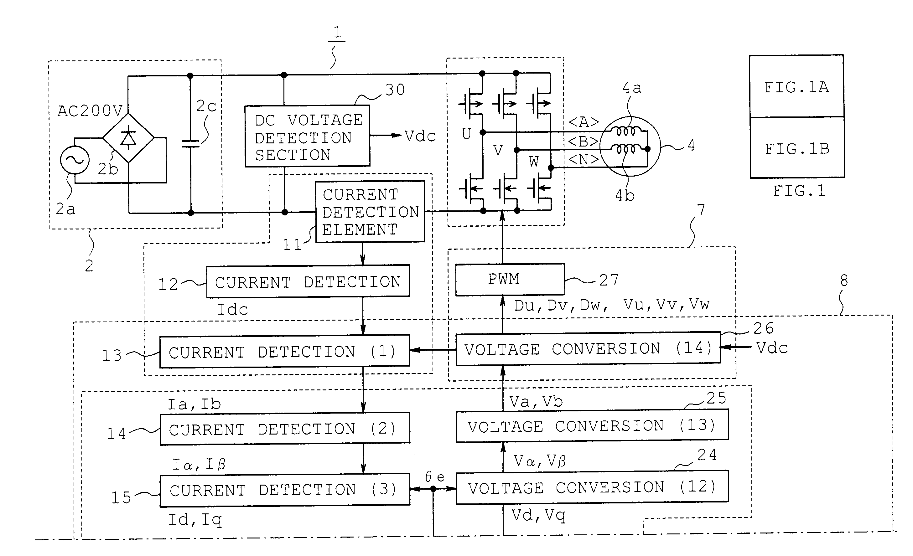
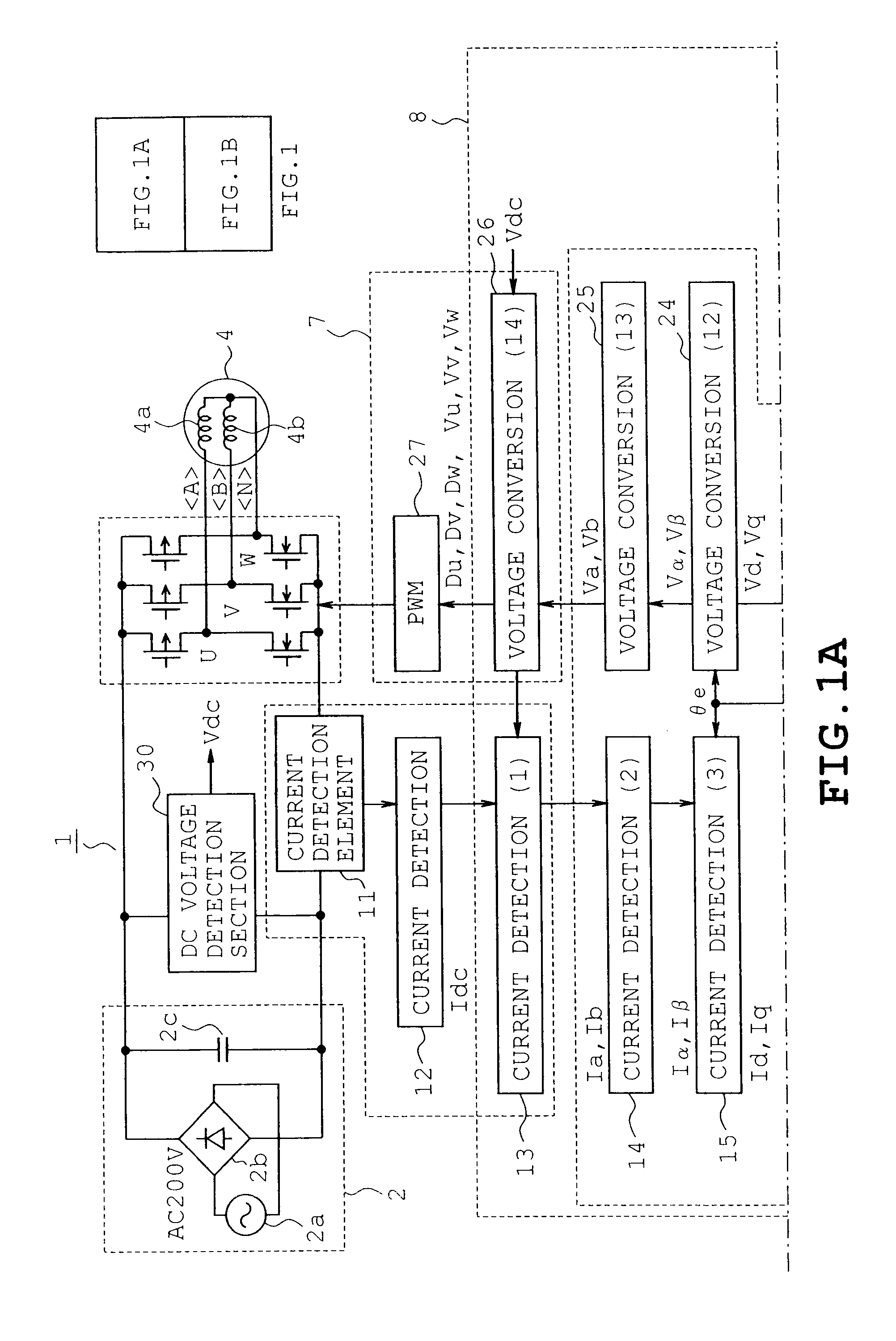
[0081] the current detecting section 5 classifies the energized state into the zone=2 in which energization is carried out only between phase B upper arm and phase N lower arm, the zone=5 in which energization is carried out between phase A upper arm and phase N lower arm, and the zone=0 in which energization is carried out in the other zones, based on the relation among the command voltages Vu, Vv and Vw or PWM duties Du, Dv and Dw. As a result, the relationship is determined among the timing of current detection, the results of the detection, the main winding current Ib, auxiliary winding current Ia, regarding each zone. Consequently, the control can be carried out in a more simplified manner.

first embodiment

[0082]The foregoing embodiments and drawings are not restrictive and can be modified in the following manners: regarding zone=0 in the first embodiment, the absolute value of the duty difference between two phases need not be set so as to be less than 2M. In short, in actual processing, the duty difference may be set to a suitable range by finding the level at which the duty difference between two phases cannot significantly be detected.

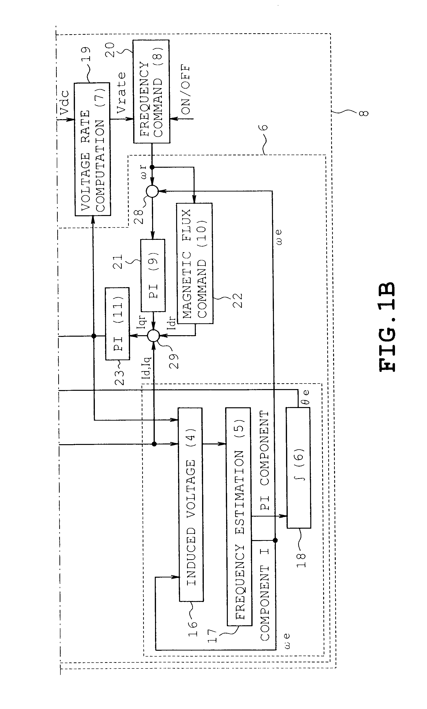
[0083]A vector control can be employed in which a slip frequency and a rotational frequency of a rotor of the induction motor are obtained by calculation without elimination.

[0084]Although the single phase 200-volt power supply is used and the 200-volt induction motor is used in each foregoing embodiment, a 100-volt induction motor may be used and a three-phase 100-volt power supply may be used, and voltage doubler rectification may be employed as the DC power supply forming section, instead.


PUM


Abstract

An inverter device driving an induction motor including main and auxiliary windings both having different winding specifications includes a three-arm inverter circuit having phase output terminals connected to the main winding, the auxiliary winding and a neutral winding of the induction motor respectively and converting a DC power supply to two-phase substantially sinusoidal PWM voltage, a current detector detecting currents of the respective main and auxiliary windings from a DC power supply current, a vector control computing unit obtaining balanced inductance values and resistance values from inductance values and resistance values of the respective main and auxiliary windings, determining a two-phase voltage to be supplied to the induction motor by vector control computing based on the balanced inductance values and resistance values, and a PWM signal forming unit forming a PWM signal controlling the inverter circuit according to the two-phase voltage.

Description

CROSS-REFERENCE TO RELATED APPLICATIONS[0001]This application is based on and claims the benefit of priority from the prior Japanese Patent Application No. 2008-216593, filed on Aug. 26, 2008, the entire contents of which are incorporated herein by reference.BACKGROUND[0002]1. Field[0003]The present invention relates to an inverter device which can drive two-phase induction motors with high efficiency.[0004]2. Related Art[0005]Electric motors used in industrial instruments and household electrical appliances need to be driven with high efficiency. Eminent techniques for this purpose include driving a brushless DC motor such as a permanent magnet motor by an inverter device. This motor-driving technique is employed in air conditioners, refrigerators and the like. However, the permanent magnet motors are expensive so that disseminating the permanent magnet motors to the world has a certain limit. On the other hand, a single-phase induction motor includes a main winding directly connec...

Claims


Application Information

Patent Timeline
Patent Type & Authority Applications(United States)
IPC IPC(8): H02P21/00H02P27/08H02M7/5387H02P21/14H02P21/18H02P21/22H02P21/24H02P23/07H02P23/14H02P25/04H02P27/04H02P27/06
CPCH02P1/426H02P27/12H02P21/0046H02P21/28
Inventor NAGAI, KAZUNOBUSHIBAYAMA, TAKESHIMAEKAWA, SARI
Owner KK TOSHIBA
Why Eureka
Try Eureka