Common mode filtering method and device

a filtering method and filtering technology, applied in the field of common mode filtering methods and devices, can solve the problems of mode choke, adversely affecting the operation of electronic systems, and increasing the complexity of the electronic system's electromagnetic environment, so as to reduce the etching area of the ground plane, simplify the fabrication process, and increase the insertion loss

Active Publication Date: 2010-03-04
NAT TAIWAN UNIV
View PDF0 Cites 31 Cited by
  • Summary
  • Abstract
  • Description
  • Claims
  • Application Information

AI Technical Summary

Benefits of technology

[0015]In the present invention, since differential mode signals and common mode signals passing through the coupled microstrip lines have different reference return path, a defected ground structure equivalent to a LC resonator can be formed on the return ground path of the common mode signals so as to suppress the common mode signals without affecting the differential mode signals. Through different defected ground structures, the present invention not only suppresses common mode noises over a wider frequency band and increases the insertion loss, but also reduces etching area of the ground plane, thereby simplifying the fabrication process, saving the fabrication cost and reducing the circuit volume.

Problems solved by technology

Along with wide application of various kinds of electronic equipments, television networks, switches, mobile communication equipments and office automation equipments, electromagnetic environment of electronic systems is becoming more complicated and EMI (Electromagnetic interference) is becoming an increasingly severe problem, which adversely affects operation of the electronic systems.
However, coupling noise interference often leads to currents of same phase in two signals, i.e., common mode currents, which are the main source of EMI and should be considered in circuit wiring and design.
However, frequency characteristic and parasitic effect of the ferromagnetic material prevents the common mode choke from operating at frequencies of GHz.
Although this method has a design concept similar to the common mode choke, its fabrication process is rather complicated and costly.
Therefore, how to provide a common mode filtering method and device with simplified fabrication process, low fabrication cost and good suppression effect has become urgent.

Method used


Image

  • Common mode filtering method and device
  • Common mode filtering method and device
  • Common mode filtering method and device

Examples


first embodiment

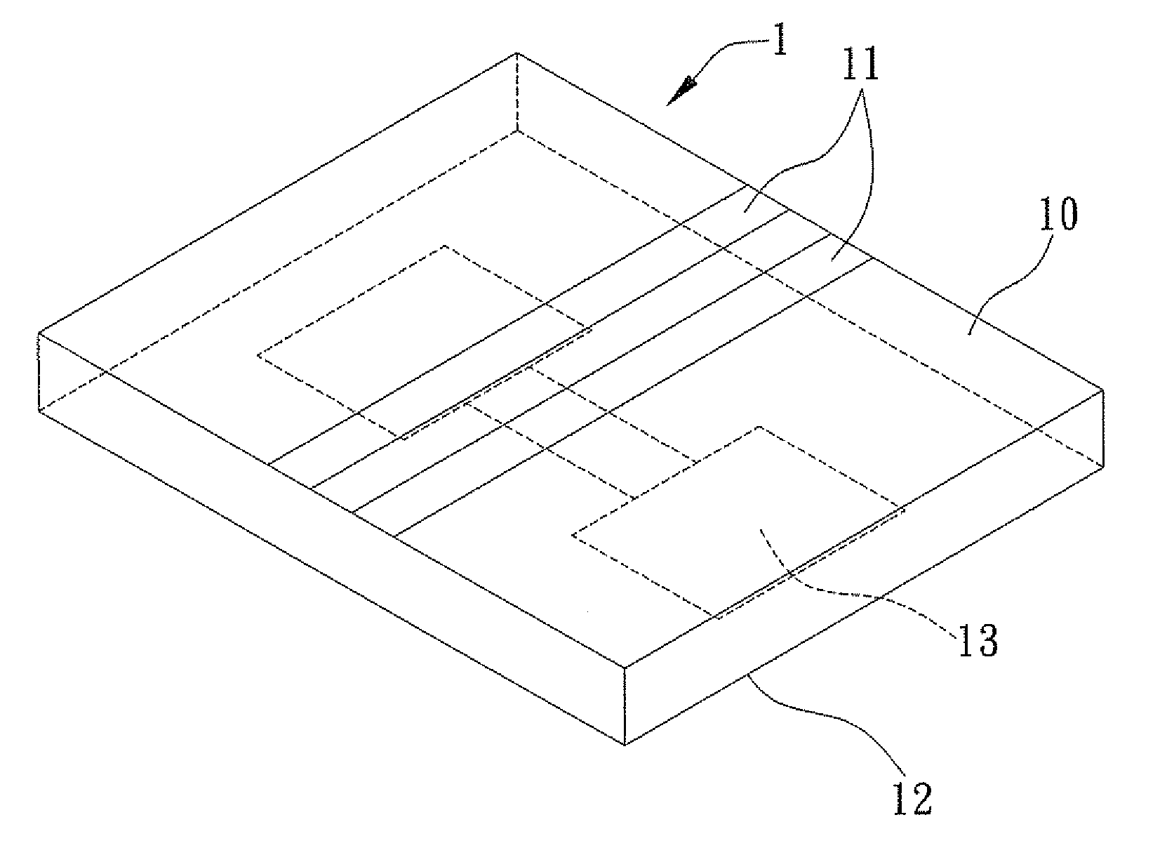
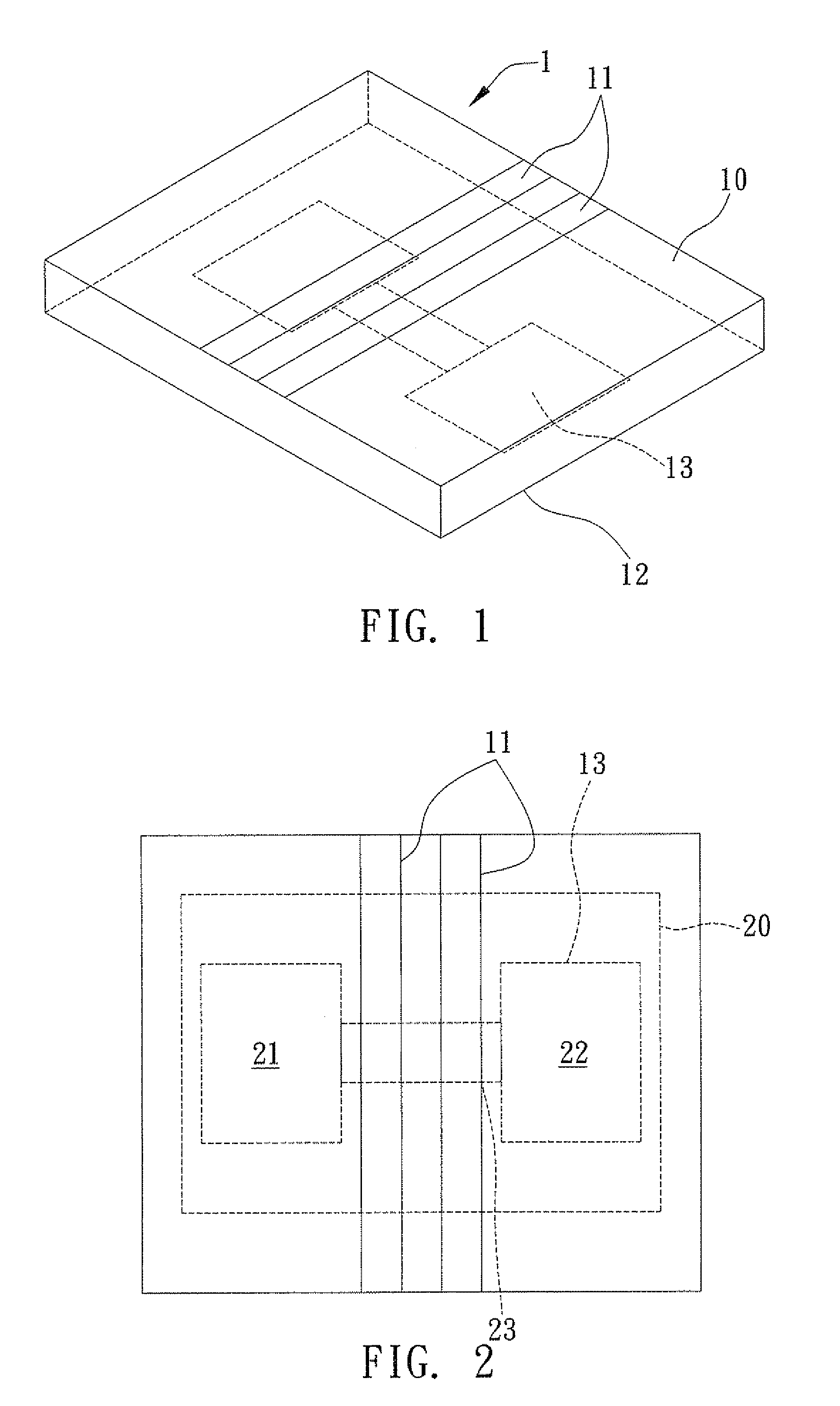
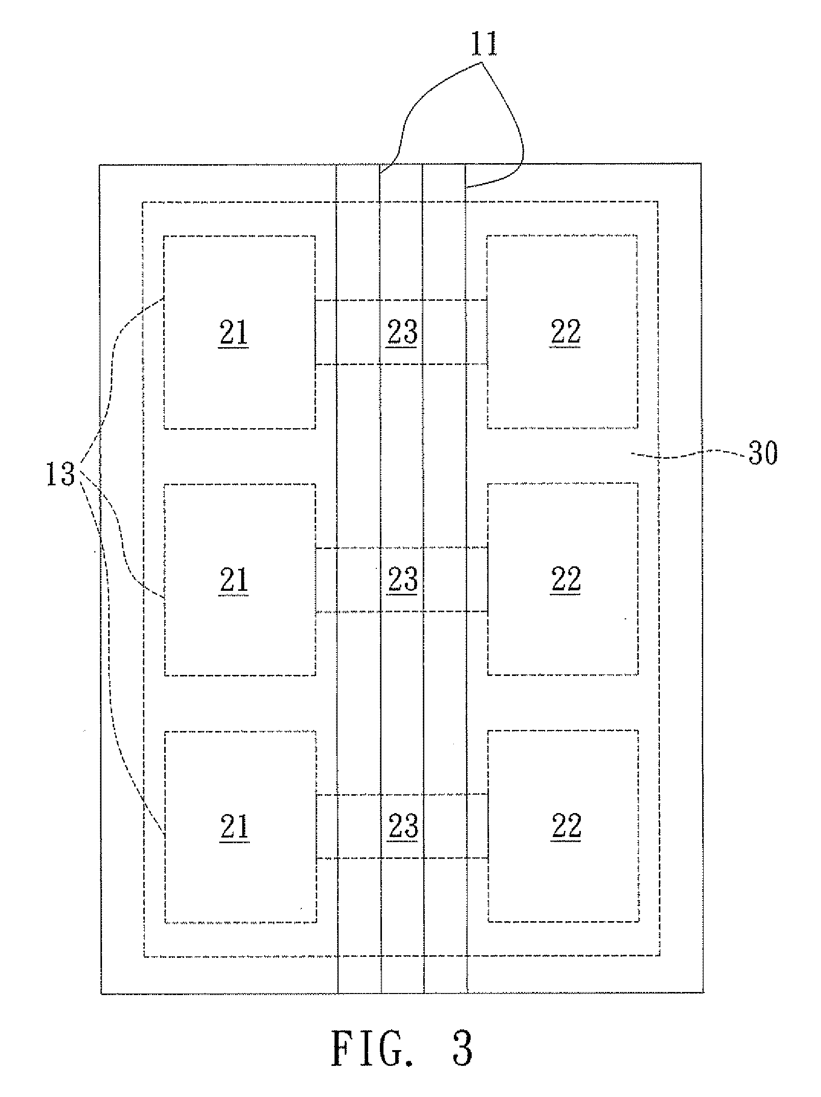
[0028]FIG. 2 shows a common mode filtering device for use with a defected ground structure according to the present invention. The defected ground structure 13 of the common mode filtering device comprises a first rectangular region 21, a second rectangular region 22 and a third rectangular region 23, wherein the first rectangular region 21 has a size same as that of the second rectangular region 22 and is parallel with the second rectangular region 22, two sides of the third rectangular region 23 connect the first and second rectangular regions 21, 22 respectively, and sides of the first and second rectangular regions 21, 22 contacting the third rectangular region 21 have a length longer than said sides of the third rectangular region 21.

[0029]In practical application, dual mode signals are passed through the coupled microstrip lines 11. The dual mode signals comprise differential mode signals and common mode signals, wherein the reference return path of the common mode signals pas...

third embodiment

[0047]In practical application, as shown in FIG. 6, the ground plane 12 has a H-shaped defected ground structure 13′ formed at the central portion thereof, and a -shaped defected ground structure and a -shaped defected ground structure respectively formed on the upper and lower portions thereof. As disclosed in the third embodiment, the -shaped defected ground structure and -shaped defected ground structure of the present embodiment can suppress the common mode signals at a wider frequency band and increase more insertion loss so as to obtain a better suppression effect. Therefore, the filter using the defected ground structure 13′ plus the -shaped and -shaped ground structures not only obtain a preferred common mode signal suppression effect, but also efficiently reduce size of electronic elements and save the fabrication cost.

[0048]FIG. 7 shows a flow process of a common mode filtering method for use with a defected ground structure according to the present invention. The common m...


PUM


Abstract

Provided are common mode filtering method and device for use with a defected ground structure, the device including a substrate, coupled microstrip lines formed on the substrate and a ground plane formed underneath the substrate, the common mode filtering method being characterized by forming at least a defected ground structure on the ground plane and making dual mode signals pass through the coupled microstrip lines, thereby using the defected ground structure to suppress dual model noises within a specific frequency band and prevent signal distortion.

Description

BACKGROUND OF THE INVENTION[0001]1. Field of the Invention[0002]The present invention relates generally to common mode filtering methods and devices, and more particularly to a method and device for use with different defected ground structures to suppress common mode noises.[0003]2. Description of Related Art[0004]Along with wide application of various kinds of electronic equipments, television networks, switches, mobile communication equipments and office automation equipments, electromagnetic environment of electronic systems is becoming more complicated and EMI (Electromagnetic interference) is becoming an increasingly severe problem, which adversely affects operation of the electronic systems.[0005]Generally, differential signals are used for high-speed data transmission, such as USB 3.0 and IEEE 1394, so as to reduce noise interference. Since differential signals generate much less noise and suppress common mode noise, signal distortion can be avoided. However, coupling noise ...

Claims


Application Information

Patent Timeline
Patent Type & Authority Applications(United States)
IPC IPC(8): H01P1/203
CPCH01P1/20336
Inventor WU, TZONG-LINWU, SHU-JUNG
Owner NAT TAIWAN UNIV
Why Eureka
Try Eureka