Switching power supply device

a power supply device and switching technology, applied in the direction of electric variable regulation, process and machine control, instruments, etc., can solve the problems of high cost and labor, difficult to determine whether the load is light or heavy based on the fb terminal voltage, etc., and achieve the effect of high efficiency and simple configuration of the switching power supply devi

Active Publication Date: 2010-03-04
SANKEN ELECTRIC CO LTD
View PDF7 Cites 15 Cited by
  • Summary
  • Abstract
  • Description
  • Claims
  • Application Information

AI Technical Summary

Benefits of technology

[0049]In accordance with the first aspect of the present invention, the highly efficient switching power supply dev

Problems solved by technology

Therefore, the switching power supply control circuit of Patent Publication 1 will always perform the predetermined intermittent operation no matter whether the load may be light or heavy, and has difficulty performing a more precise output control.
Therefore, it is difficult to determine whethe

Method used


Image

  • Switching power supply device
  • Switching power supply device
  • Switching power supply device

Examples


embodiment 1

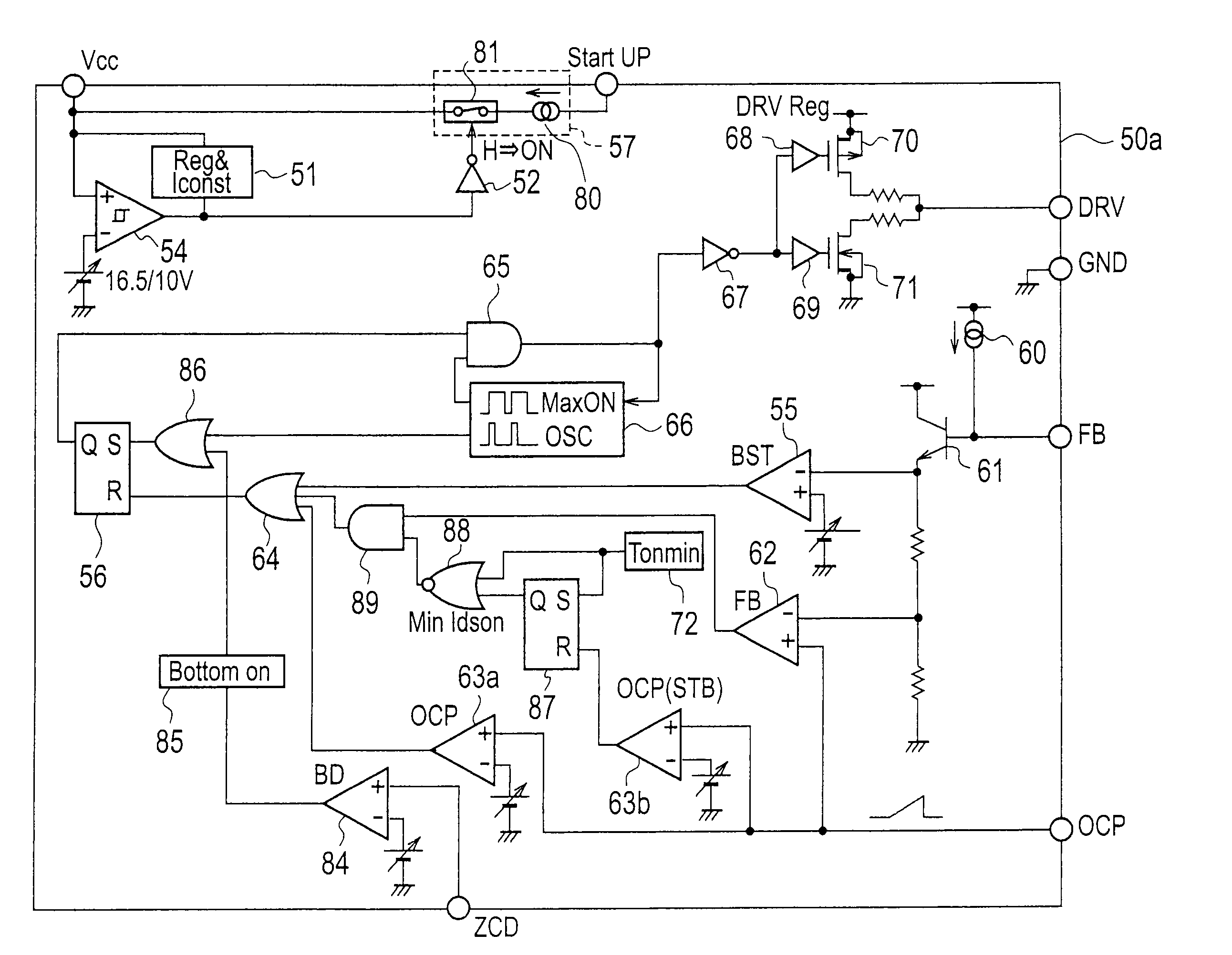
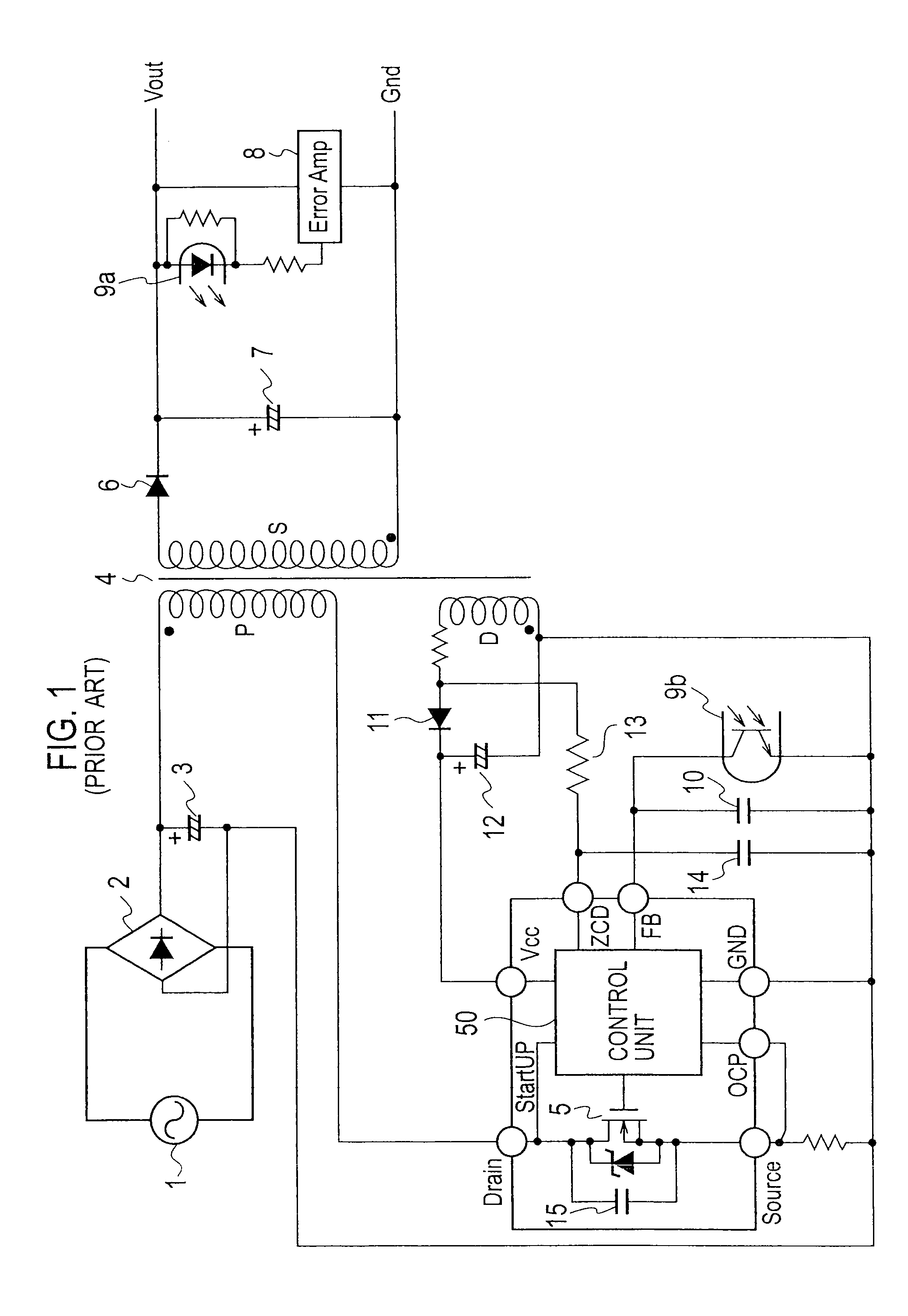
[0067]An entire configuration of a switching power supply device according to Embodiment 1 of the present invention is substantially similar to that of the quasi-resonant switching power supply device shown in FIG. 1. In Embodiment 1, the quasi-resonant control unit 50 shown in FIG. 1 is replaced by a control unit 50a described in FIG. 5.

[0068]The control unit 50a as a control circuit of the switching power supply device according to Embodiment 1 of the present invention controls ON / OFF of the switching element 5. The switching power supply device according to Embodiment 1 includes: the transformer 4 that has the primary winding P, the secondary winding S and the auxiliary winding D; the switching element 5 connected to the primary winding P of the transformer 4; the control unit 50a that performs the ON / OFF control for the switching element 5 in the case where the voltage is inputted to the primary side of the transformer 4; the rectifying / smoothing circuit that rectifies and smoot...

embodiment 2

[0097]FIG. 13 is a diagram showing a configuration of a switching power supply device according to Embodiment 2 of the present invention. Note that an entire configuration of the switching power supply device according to Embodiment 2 is substantially similar to that of the switching power supply device according to Embodiment 1. The switching power supply device according to Embodiment 2 is different from the switching power supply device according to Embodiment 1 in that a constant current source 90 and a second switch 91, which are for supplying a compensation constant current, are provided in the control unit 50a, and that a detecting resistor Rocp, an adjusting resistor Rfocp and a noise removing capacitor Cfocp are provided on an outside of the control unit 50a.

[0098]The constant current source 90 supplies the constant current to the OCP terminal in the case where the second switch 91 is turned on. Moreover, the second switch 91 turns on during a period since DRV is turned on...

embodiment 3

[0110]FIG. 15 is a circuit diagram showing a configuration of a control unit 50b of a switching power supply device according to Embodiment 3 of the present invention. Note that an entire configuration of the switching power supply device according to Embodiment 3 is substantially similar to that of Embodiment 1 or that of the conventional switching power supply device described by using FIG. 1. In Embodiment 3, the control unit 50a in Embodiment 1 is replaced by a control unit 50b to be described with reference to FIG. 15. The control unit 50b in Embodiment 3 is different from the control unit 50a of the switching power supply device according to Embodiment 1 in that the control unit 50b does not have the pulse generator 72, the second OCP comparator 63b, the second flip-flop 87 or the NOR circuit 88, and instead of these, includes therein a first pulse generator 92, a second pulse generator 93, a voltage sensor 94, a third switch 95, and a third inverter 96.

[0111]The first pulse g...


PUM


Abstract

A switching power supply device includes: a transformer that has a primary winding and a secondary winding; a switching element connected to the primary winding of the transformer; a control circuit that controls the switching element to be turned on/off in a case where a voltage is inputted to the primary winding of the transformer, and thereby induces a voltage in the secondary winding of the transformer; and a rectifying/smoothing circuit that rectifies and smoothes the voltage induced in the secondary winding of the transformer, and outputs the rectified and smoothed voltage to a load. The control circuit has: a current control unit that controls the switching element to prevent a current flowing through the switching element from being lowered to a fixed value or less in a case where the load is light; and an intermittent control unit that, in the case where the load is light, controls the switching element to perform an intermittent oscillation operation based on a feedback signal corresponding to an output voltage to the load.

Description

BACKGROUND OF THE INVENTION[0001]1. Field of the Invention[0002]The present invention relates to a switching power supply device that generates and outputs a predetermined voltage by a switching operation, and is capable of a stable control at a time when a load is light.[0003]b 2. Description of the Related Art[0004]A switching power supply device that controls an output voltage by performing an ON / OFF control for a switching element has been heretofore used for OA equipment, consumer appliances and the like. In recent years, efficiency enhancement of the switching power supply device has been required from viewpoints of considering the environment and saving energy. A control circuit that controls the switching element in the switching power supply device is usually composed of a one-chip integrated circuit, and includes, in an inside of the integrated circuit, a starting circuit for starting the integrated circuit concerned.[0005]A conventional quasi-resonant switching power supp...

Claims


Application Information

Patent Timeline
IPC IPC(8): H02M3/335
CPCH02M3/33507Y02B70/16H02M2001/0032Y02B70/10H02M1/0032
Inventor SHIMADA, MASAAKI
Owner SANKEN ELECTRIC CO LTD
Why Eureka
Try Eureka