Adaptive optic beamshaping in laser processing systems

Inactive Publication Date: 2010-03-11
ELECTRO SCI IND INC
View PDF10 Cites 22 Cited by
  • Summary
  • Abstract
  • Description
  • Claims
  • Application Information

AI Technical Summary

Benefits of technology

[0005]Thus, certain embodiments disclosed herein include a laser processing system that quickly and flexibly modifies the processing beam to determine and implement an improved or optimum beam profile for a particular application (or a subset of the application). The system reduces the sensitivity of beam shaping sub

Problems solved by technology

The system reduces the sensitivity of beam shaping subsystems to variations in the laser processing system, including those

Method used


Image

  • Adaptive optic beamshaping in laser processing systems
  • Adaptive optic beamshaping in laser processing systems
  • Adaptive optic beamshaping in laser processing systems

Examples


Example

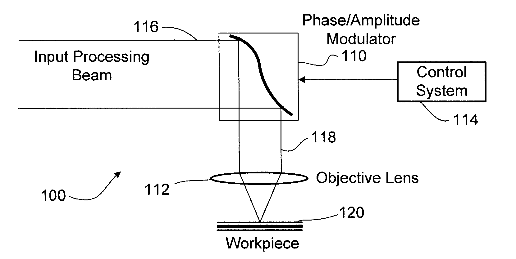
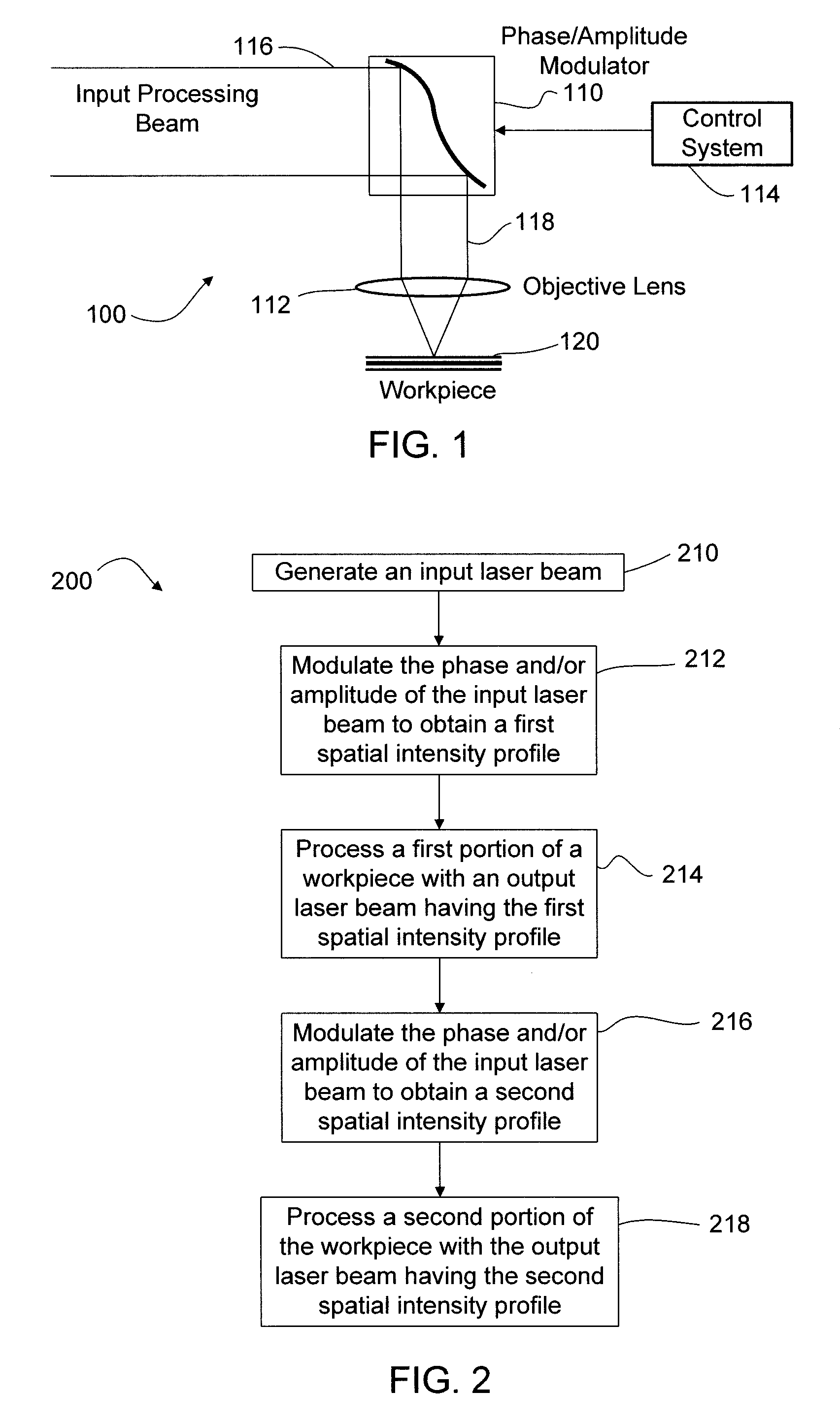
[0018]Adaptive optics are integrated into an optical train of a laser processing system to flexibly and rapidly shape the spatial intensity profile of the processing beam. The adaptive optics are configured to phase modulate and / or amplitude modulate the laser beam so as to rapidly switch between two spatial intensity profiles. While both phase and / or amplitude modulation may be used in the embodiments discussed herein, phase modulation may be preferred in certain embodiments due to its ability to maintain a relatively higher optical efficiency than that of amplitude modulation. The time used by the laser processing system to change its output from a first spatial intensity profile to a second spatial intensity profile may be referred to herein as a “switching time.” In one embodiment, for example, the switching time of the laser processing system is in a range between approximately 100 μs and approximately 5 ms. An artisan will recognize from the disclosure herein that other switch...


PUM

PropertyMeasurementUnit
Timeaaaaaaaaaa
Timeaaaaaaaaaa
Orderaaaaaaaaaa

Abstract

A laser processing system quickly and flexibly modifies a processing beam to determine and implement an improved or optimum beam profile for a particular application (or a subset of the application). The system reduces the sensitivity of beam shaping subsystems to variations in the laser processing system, including those due to manufacturing tolerances, thermal drift, variations in component performance, and other sources of system variation. Certain embodiments also manipulate lower quality laser beams (higher M2 values) to provide acceptable shaped beam profiles.

Description

TECHNICAL FIELD[0001]This disclosure relates to laser processing. More particularly, this disclosure relates to using adaptive optics to rapidly change the shape of a spatial intensity profile of a laser beam during material processing.BACKGROUND INFORMATION[0002]Many laser processing systems use a process spot with a specified spatial intensity profile at a work surface to optimize a particular laser process. Beamshaping methods for producing the desired spatial intensity profile include, for example, using diffractive and refractive optic elements. These approaches pose design challenges, however, due to restrictive input laser beam tolerances (e.g., for position, diameter, mode quality, and other parameters) generally required to maintain acceptable output beam characteristics. Production laser processing systems are generally designed to meet such output laser beam characteristics despite variations in input laser beam characteristics and / or laser beam delivery optics. Such vari...

Claims


Application Information

Patent Timeline
IPC IPC(8): B23K26/06
CPCB23K26/0613B23K26/426B23K26/0676B23K26/0656B23K26/705B23K26/066B23K26/064G02B27/09B23K26/70
Inventor UNRATH, MARK A.PIROGOVSKY, PETERBALDWIN, LEO
Owner ELECTRO SCI IND INC
Why Eureka
Try Eureka