Method and Apparatus for Improving Image Resolution

a technology of image resolution and apparatus, applied in the field of methods and apparatus for improving image resolution, can solve the problems of reducing the signal quickly, affecting the image resolution, and the cost of buying and maintaining, so as to improve the axial (z) discrimination or resolution, improve the image resolution, and improve the resolution

Inactive Publication Date: 2010-03-11
KING'S COLLEGE LONDON
View PDF5 Cites 36 Cited by
  • Summary
  • Abstract
  • Description
  • Claims
  • Application Information

AI Technical Summary

Benefits of technology

[0021]The present invention provides a new technique to apply the resolution enhancing effect identified by Sandeau et al. in the context of the 4Pi microscope more broadly to other image generation systems, and in particular to standard confocal microscopes. In particular, embodiments of the present invention will allow the operation of confocal microscopes with relatively open pinholes (e.g. 1 Airy unit or even without any pinhole) whilst still giving a significant XY resolution improvement. In addition axial (Z) discrimination or resolution may also be improved. Embodiments of the invention achieve this aim by splitting the emitted light path in an interferometric fashion at a position in the standard system it would normally not be split. This would typically be after the objective and after the (de-)scanning optics but before the pinhole or another spatially discriminating detector. At least one of the split beams is then directed to an image transformation system, which applies an image transformation which spatially displaces those parts of the image which are not on or near the optical axis within the image plane. For example, the image transformation may be an image inversion which inverts at least one coordinate in image space. The transformed beam and the non-transformed beam are then recombined in an interferometric fashion (i.e. coherently added), which provides an interference effect resulting in increased resolution of the image. Where the embodiments are being used in a confocal application, the resulting combined beam is then typically subject to a spatially discriminating means, such as an adjustable pinhole, or the like. However this is not strictly necessary as the main effect stems from the loss of light to the other output-path of the interferometer once the amplitudes of the interfering beams differ.

Problems solved by technology

When the distance between the luminophore and the optical axis increases, D and ID′ separate laterally giving rise to partially destructive interference, which rapidly lowers the signal.
However, 4Pi microscopes are relatively rare, being expensive to buy and maintain.
's work in the context of the 4Pi microscopes, whilst interesting, does not solve the problem faced by many research labs worldwide, of how to improve the resolution of the more standard and (in comparison to the 4Pi microscope) common confocal microscope or widefield microscope.
The described confocal interferometer has the drawback of having very unequal optical pathlength and thus requiring a very long coherence length to observe interference effects.
RSI does not make use of the fact that the on-axis position can yield completely uniform (e.g. constructive) interference, whereas off-axis positions yield non-uniform coherence and thus lose light to the other path of the interferometer.
An image plane close to the detector would pose problems to conventional RSI.
Furthermore RSI does not have the purpose of improving the resolution and / or optical sectioning capability of an imaging system.

Method used


Image

  • Method and Apparatus for Improving Image Resolution
  • Method and Apparatus for Improving Image Resolution
  • Method and Apparatus for Improving Image Resolution

Examples


first embodiment

[0092]The illuminating beam (excitation beam) reflected from the XY scan mirror 88 passes through the scan lens (SL) (90) and then the tube lens TL (92). The scan lens serves in combination with the tube lens in a 4-f configuration to keep the light intensity distribution at the back focal plane of the objective lens 94 independent of the scan position. The alteration in angle of the beam due to the XY scan mirror then translates the scanning spot in the sample plane. The emitted light (which may either be scattered light, or fluorescence) passes through the objective lens system (94), the tube lens 92, and the scan lens 90, is then de-scanned by the XY scan mirror 88, and directed towards the dichromatic mirror 86. As mentioned, the dichromatic mirror can be arranged to reflect light at the wavelength of the illuminating (excitation) beam, but not to reflect light at the wavelength of the emitted light. Thus, the emitted light passes through the dichromatic mirror 86, and then into...

third embodiment

[0098]More particularly, within the third embodiment the interferometer is of the Michelson type, which means that the same beam splitting element is used for both splitting and recombining the beams.

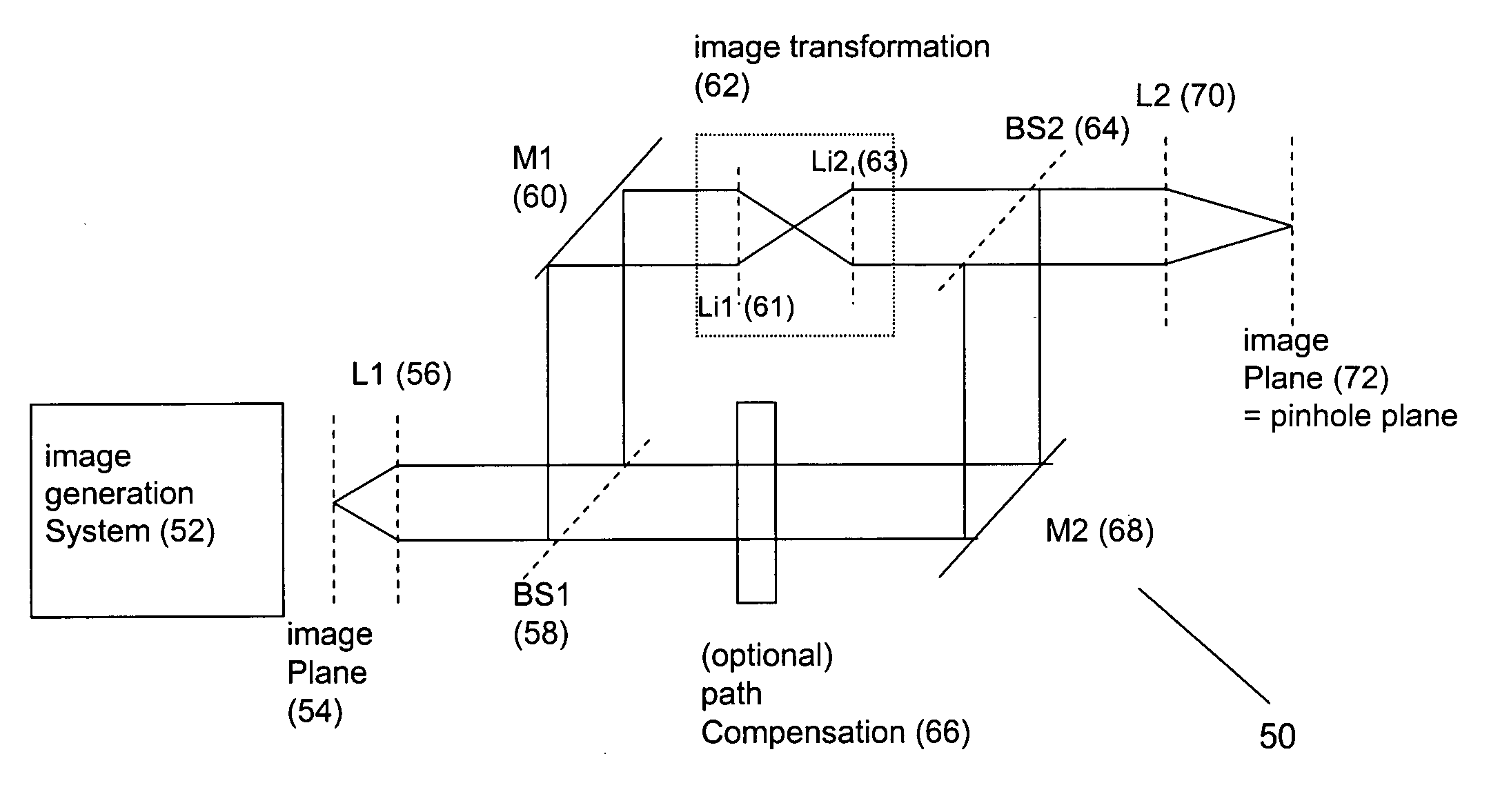
[0099]More particularly, with reference to FIG. 8 an apparatus 100 according to the third embodiment of the present invention comprises a first lens L1 (56) arranged to receive light from the input image plane 54. The lens L1 produces a parallel beam representing a point in the image plane 54, and directs the parallel beam towards the beam splitter BS1 (58). The beam splitter 58 provides a first output beam corresponding to the transmission of the beam through the beam splitter, and a second output beam corresponding to a reflection of the input beam from the beam splitter. The first output beam is directed towards an image inversion system, which provides an image transformation in the form of an image inversion. More particularly, the image inversion system comprises a lens Li1 (102) ...

fourth embodiment

[0107]the invention will now be described with respect to FIG. 9.

[0108]Within the fourth embodiment an image resolution enhancing apparatus 110 is provided, based upon the Michelson interferometer arrangement of the third embodiment, and described previously. However, within the fourth embodiment the image transformation system is a different arrangement, the lens L11 and mirror M2 of the third embodiment being replaced by an image inverting mirror Mi1 (112). The image inverting mirror Mi1 may be formed from two mirrors joined with a relative angle of 90°, or by an appropriately cut prism. The transformation obtained by such a mirror (or prism) would be that only one direction of the image would be inverted e.g. the positive X direction in the image would become negative X.

[0109]In a variation, instead of being only two mirrors, (or sides of a prism), in a variant three mutually perpendicular mirrors could be used, or an appropriately cut 90° corner prism based on total internal ref...


PUM


Abstract

Embodiments of the invention allow the operation of confocal microscopes with relatively open pinholes (e.g. 1 Airy unit) whilst still giving a significant XY resolution improvement. In addition axial (Z) discrimination or resolution may also be improved. This is achieved by splitting the emitted light path in an interferometric fashion. One of the split beams is then directed inversion which inverts at least one coordinate in image space. The transformed beam and the non-transformed beam are then recombined in an interferometric fashion (i.e. coherently added), which provides an interference effect resulting in increased resolution of the image. Where the embodiments are being used in a confocal application, the resulting combined beam can then be subject to a spatially discriminating means, such as a pinhole, or the like.

Description

TECHNICAL FIELD[0001]The present invention relates to a method and an apparatus which improve the resolution obtainable from imaging systems which use wave-based information carriers. In particular the present invention relates to a method and apparatus which employ interferometric techniques to achieve an increase in the resolution obtainable from the imaging system without sacrificing image brightness.BACKGROUND TO THE INVENTION[0002]Laser scanning confocal microscopes have been known for many years, and provide the ability to image a relatively narrow focal plane within a sample. By then adjusting the position of the microscope with respect to the sample so as to take a slightly different focal plane, a “stack” of optically sectioned images can be obtained at different positions through the sample, thus allowing a three-dimensional image of the sample to be built up. An example laser scanning confocal microscope is shown in FIG. 5.[0003]Here, a light source in the form of a laser...

Claims


Application Information

Patent Timeline
Patent Type & Authority Applications(United States)
IPC IPC(8): G01B9/02G06K9/32G02B21/36
CPCG02B21/0056
Inventor HEINTZMANN, RAINERWICKER, KAI
Owner KING'S COLLEGE LONDON
Why Eureka
Try Eureka