Method and device for an imaging ultrasonic inspection of a three-dimensional workpiece

an imaging ultrasonic and workpiece technology, applied in response signal detection, analyzing fluids using sonic/ultrasonic/infrasonic waves, and using phased array methods for non-destructive materials, etc., can solve the problem of high expenditure of time for the complete material test, the need for a new focal position and a new acoustic irradiation angle also requires labor-intensive and time-consuming reprogramming process, and achieves high measuring speed speed problem

Active Publication Date: 2010-03-18
FRAUNHOFER GESELLSCHAFT ZUR FOERDERUNG DER ANGEWANDTEN FORSCHUNG EV
View PDF11 Cites 13 Cited by
  • Summary
  • Abstract
  • Description
  • Claims
  • Application Information

AI Technical Summary

Benefits of technology

[0022]The high measuring and evaluation speeds achieved with the invention also make it possible to acoustically irradiate workpieces that move along a production line with transport speeds of a few m/sec, for example, up to 10 m/sec, in the above-described measuring mode, that is, the workpieces are acoustically irradiated by all ultrasonic transducers in individual successive measuring cycles in order to obtain meaningful sectional image

Problems solved by technology

The disadvantages of utilizing the phased array method for a non-destructive material inspection on a test body, however, can be seen in the expenditure of time and the metrological expenditure until a test body is inspected in a largely complete fashion, namely because it is essential for a complete signal evaluation to obtain sufficiently reliable measuring signals from all regions of the test body volume.
Consequently, an inspection of the entire test body volume requires a very large number of measurements with respectively different phase controls such that the expenditure of time for the complete material test is quite high.
The adjustment of a new acoustic irradiation angle or a new focal position also requires a labor-intensive and time-consuming reprogramming process.
Another disadvantage can be seen in that a predefined acoustic irradiation angle specifies the probe aperture, that is, the aperture cannot be optimally chosen for all acoustic irradiation angles such that the resolution of the measurements deteriorates.
As initially mentioned, online inspections of workpieces in the form of extruded profiles that are transported or conveyed along production lines with speeds of a f

Method used


Image

  • Method and device for an imaging ultrasonic inspection of a three-dimensional workpiece
  • Method and device for an imaging ultrasonic inspection of a three-dimensional workpiece

Examples


Embodiment Construction

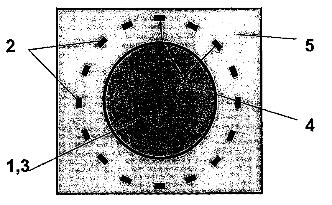
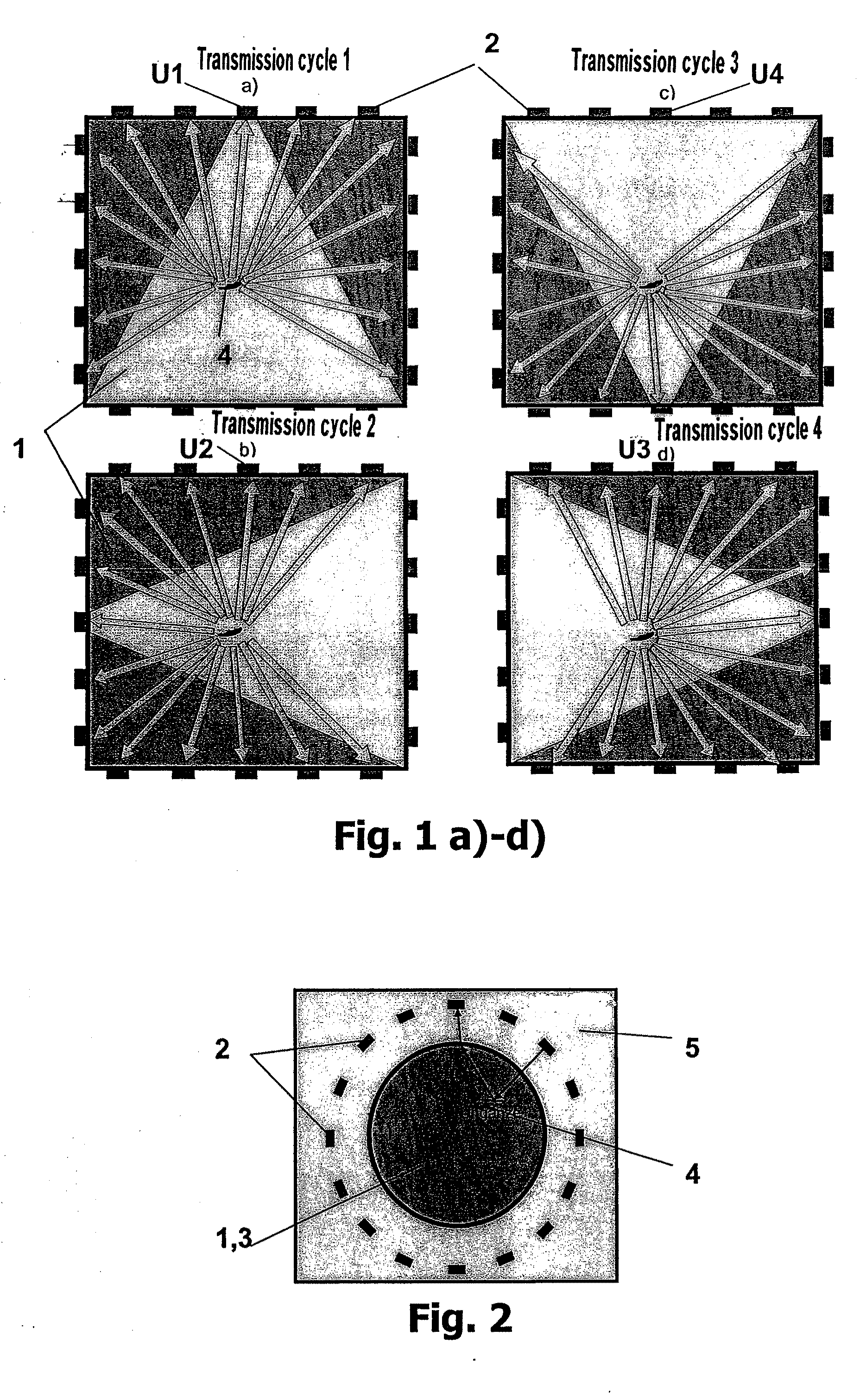
[0028]With respect to a pictorial explanation of the invention, reference is made to the transmission cycles 1 to 4 according to the illustrations shown in FIGS. 1a to d. It is assumed that the ultrasonic transducers 2 uniformly distributed around the lateral edges of an oblong workpiece 1 are in the form of an array system, that is, the number of individual ultrasonic transducers can be individually activated in a time-delayed fashion as required for the transmission and reception mode according to the Sampling Phased-Array technique. The longitudinal direction of the workpiece 1 is, for example, in the form of an extruded steel profile with square cross section is oriented perpendicular to the plane of projection of FIG. 1.

[0029]In a first transmission cycle that is illustrated in FIG. 1a, a first ultrasonic transducer U1 is activated, wherein the transmission aperture of the ultrasonic transducer has a shape that diverges in a cone-shaped fashion. The ultrasonic waves reflected o...


PUM


Abstract

A method for an imaging ultrasonic inspection of a three-dimensional workpiece, in which ultrasonic waves are coupled into the workpiece with at least one ultrasonic transducer and ultrasonic waves reflected within the workpiece are received by ultrasonic transducers and converted into ultrasonic signals forming the basis of the non-destructive imaging ultrasonic inspection.

Description

BACKGROUND OF THE INVENTION[0001]1. Field of the Invention[0002]The invention pertains to a method for an imaging ultrasonic inspection of a three-dimensional workpiece, in which ultrasonic waves are coupled into the workpiece with one ultrasonic transducer or a number of ultrasonic transducers and ultrasonic waves reflected within the workpiece are received by a number of ultrasonic transducers and converted into ultrasonic signals forming the basis of the non-destructive imaging ultrasonic inspection.[0003]2. Description of the Art[0004]The non-destructive inspection of a test body by means of ultrasound, for example, for testing materials for material defects such as cracks, inclusions or other material nonhomogeneities comprises the coupling of ultrasonic waves into the test body, the detection of the ultrasonic waves that are transmitted through the test body or reflected, diffracted, scattered and / or refracted within the test body, as well as the evaluation of the ultrasonic w...

Claims


Application Information

Patent Timeline
IPC IPC(8): G01N29/04
CPCG01N29/0645G01N29/11G01N2291/106G01N29/38G01N2291/105G01N29/28
Inventor KRONING, MICHAELBOULAVINOV, ANDREIREDDY, KRISHNA MOHANVON BERNUS, LUDWIG
Owner FRAUNHOFER GESELLSCHAFT ZUR FOERDERUNG DER ANGEWANDTEN FORSCHUNG EV
Why Eureka
Try Eureka