Dedicated Superconductor MRI Imaging System

a superconductor magnetic resonance imaging and imaging system technology, applied in the direction of magnetic resonance measurement, acoustic wave reradiation, measurement devices, etc., can solve the problems of large fov, high sample noise, and conflicting ideal transmission coils with receiver coils, so as to improve imaging quality

Active Publication Date: 2010-03-18
TIME MEDICAL HLDG
View PDF12 Cites 61 Cited by
  • Summary
  • Abstract
  • Description
  • Claims
  • Application Information

AI Technical Summary

Benefits of technology

[0013]One objective in accordance with the present invention is to construct a dedicated MRI imaging apparatus with a high quality superconductor imaging coil integrated with a cryogenic system to improve imaging quality.
[0014]Another objective is to provide a compact MRI imaging system with a local examination region to improve signal-to-noise ratio.
[0015]A further objective is to improve efficiency of MRI imaging procedure with a fixed coil system for patients in a clinic environment.

Problems solved by technology

However, criteria of an ideal transmission coil conflict with those of the receiver coil.
The larger the sample is, the higher the sample noise will be.
Large coils have large FOVs and create high sample noise and coil noise.
The drawback of the superconductor coil is that one has to use a bulky cryogenic subsystem in order to operate the superconductor coil.
With the bulky cryogenic subsystem, it is very troublesome to do the installation which limits the application.
Many old designs for the general purpose scanner such as coils, cryogenic (cooling) system for the coils, the housing for the coils and the patient support are no longer suitable for the new, high performance MRI system.

Method used


Image

  • Dedicated Superconductor MRI Imaging System
  • Dedicated Superconductor MRI Imaging System
  • Dedicated Superconductor MRI Imaging System

Examples


Embodiment Construction

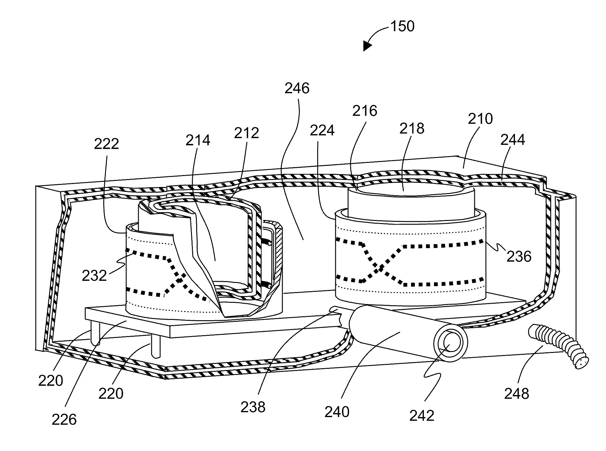
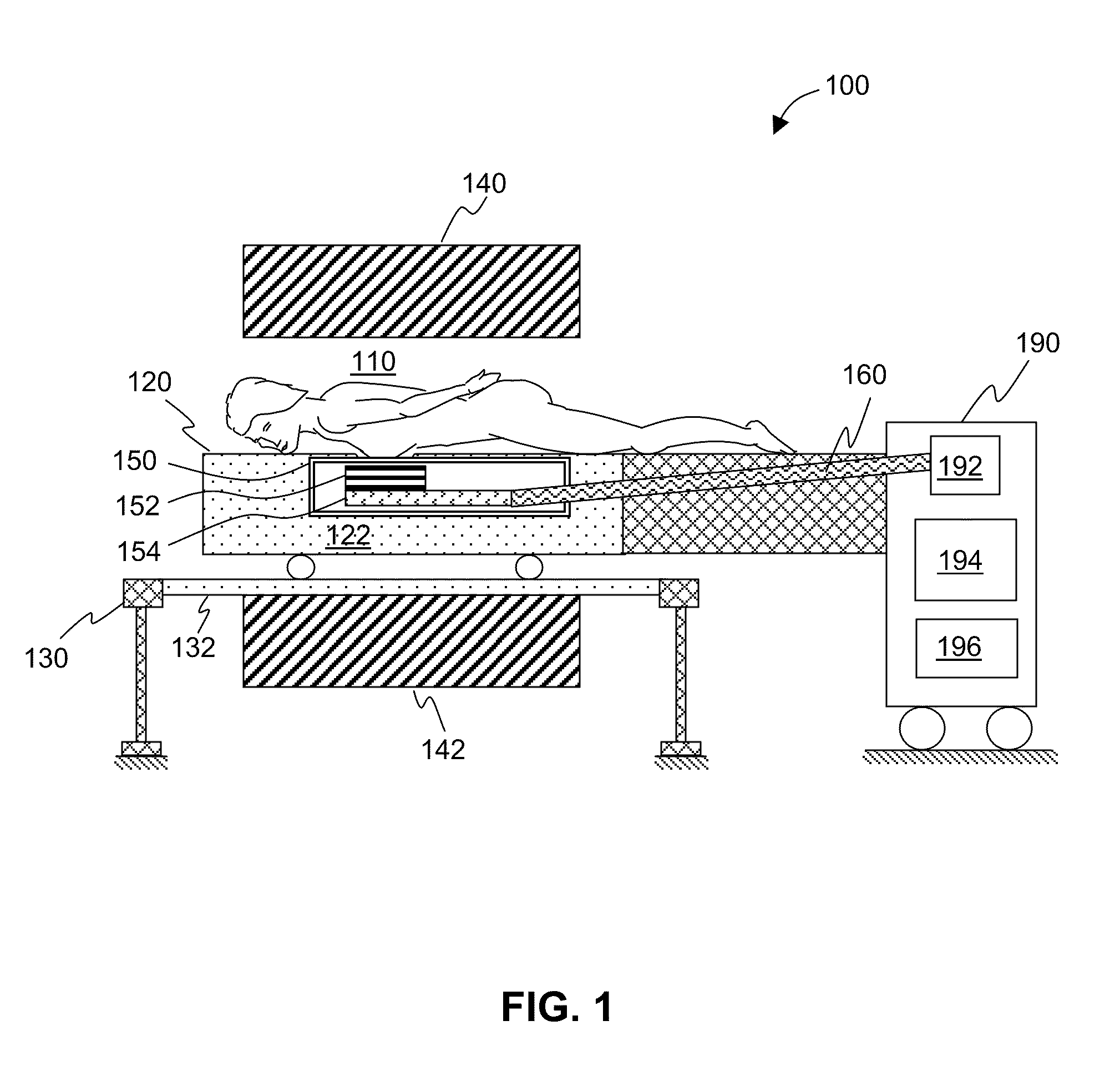
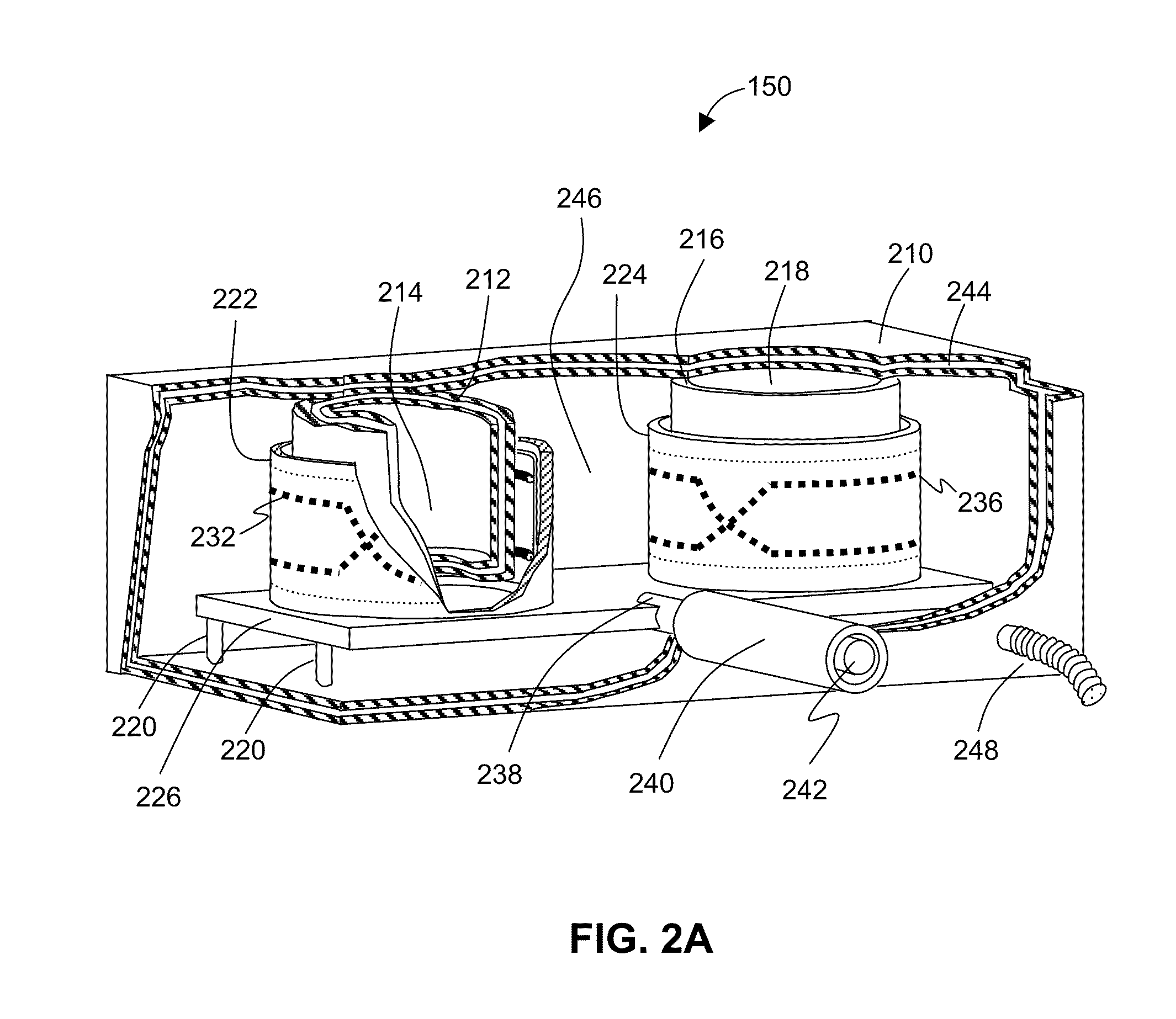
[0024]In view of the forgoing problems with conventional MRI RF systems, new designs of dedicated MRI apparatuses are needed. A dedicated MRI system requires a local examination region. According to Equation 2, when the examination volume is reduced, the noise level will be reduced. Small surface coils can achieve a higher SNR because they receive noise from a small sample volume. The disadvantage of small surface coils, however, is a limited FOV and an inhomogeneous spatial uniformity as a transmitter. Larger coils with inherently larger FOVs have the advantage of improved uniformity. It is therefore advantageous to have a two-coil system. A larger coil will be used to transmit while the superconductor coil is used as the receive coil.

[0025]Phased array surface coils have been developed to overcome the problem of decreased FOV. Phased array surface coil consists of multiple non-interacting coils, which provides a similar SNR as a small coil and an FOV associated with a larger coil ...


PUM


Abstract

The present invention relates to dedicated superconductor magnetic resonance imaging (MRI) RF apparatus and method of constructing the same. One Embodiment of the present invention provides an MRI breast imaging apparatus comprising an examination region, a patient support, at least one vacuum thermal isolation housing, a main magnet system, and a cryogenic system. The vacuum thermal isolation housing comprises a low vacuum space between at least one inner and an outer high vacuum enclosure. The low vacuum space hosts at least one superconductor RF coil and a heat sink assembly therein. The RF coil is in thermal contact with the heat sink assembly that is coupled to the cryogenic system through a heat pipe to achieve and maintain a desired low temperature at the superconductor RF coil. The system provides a local examination region substantially surrounded by the superconductor RF coil.

Description

FIELD OF INVENTION[0001]The present invention relates to superconductor magnetic resonance imaging (MRI) apparatus and method of constructing the same.BACKGROUND OF INVENTION[0002]Magnetic resonance imaging (MRI) is a noninvasive medical imaging technique widely used in radiology to visualize the structure and function of a human body or a living object. Because MRI scanner is able to create excellent images of various kinds of tissues of the body, especially the soft tissue due to the water content differences in those tissues, it provides doctors useful diagnostic information pertaining all parts of the body such as nervous system, musculoskeletal system, cardiovascular system, digestive system, and urinary reproductive system. This technique is particularly advantageous for early detection and treatment of stroke, real-time observation of cardiovascular function, and diagnosis of tumors and cancer. In addition, it is an exceptional tool for orthopedic injury diagnosis and surgery...

Claims


Application Information

Patent Timeline
Patent Type & Authority Applications(United States)
IPC IPC(8): G01R33/34
CPCG01R33/307G01R33/34023G01R33/3403G01R33/365G01R33/34069G01R33/341G01R33/3415G01R33/34046
Inventor GAO, ERZHENMA, QIYUANYEUNG, SZE MAN
Owner TIME MEDICAL HLDG
Why Eureka
Try Eureka