Abnormal current preventive circuit of dc-dc converter

a dc-dc converter and preventive circuit technology, applied in pulse manipulation, pulse technique, instruments, etc., can solve the problems of affecting the operation of the dc-dc converter, the effect of avoiding the destruction of the switching device, enhancing the area efficiency of manufacturing the device, and keeping a wasteful margin for the switching devi

Inactive Publication Date: 2010-03-18
FUJI ELECTRIC CO LTD
View PDF6 Cites 29 Cited by
  • Summary
  • Abstract
  • Description
  • Claims
  • Application Information

AI Technical Summary

Benefits of technology

[0021]The present invention aims at providing an abnormal current preventive circuit of a DC-DC converter having a smaller circuit with a shorter delay, and a less influence in device variance.
[0025]Thus, the present invention prevents an abnormal current such as an overcurrent, a countercurrent, etc. by a current comparator. Therefore, for example, when it is used for preventing an overcurrent, an abnormal current flowing through a switching device is quickly restricted to avoid the destruction of the switching device, enhance the area efficiency in manufacturing a device by a semiconductor because it is not necessary to keep a wasteful margin for a switching device, and reduce the cost.
[0026]In addition, according to the present invention, a countercurrent of an inductance current is substantially cut off when it is applied to prevent a countercurrent, thereby realizing reduced fluctuation in output voltage, a stable operation, an improved efficiency, and lower power consumption.

Problems solved by technology

However, the delay time of the voltage comparator cannot be avoided, and the ideal operation cannot be expected.
Since the recent tendency of DC-DC converters is the clock frequency of 1 MHz or more, that is, the switching period of 1000 ns or less, the influence has become serious.
That is, the fluctuation of the output voltage of the DC-DC converters has become large, thereby degrading operation efficiency.
There is a similar problem with the overcurrent of an inductor where, for example, a voltage comparator shown in FIG. 1 is applied as is to a boost type DC-DC converter.
The required resistance cannot be manufactured by an IC.
However, the delay time of the voltage comparator cannot be actually avoided, and the ideal operation cannot be expected.
The delay time with the above-mentioned conventional voltage comparator fluctuates depending on the device characteristic normally caused by the manufacturing process of an IC, it is necessary to set a large margin, thereby causing the problem that the sizes of the switching devices shown in FIGS. 1 and 2 unnecessarily increase and that the cost also increases.
In addition, when the bias current is increased to shorten the delay time in the conventional voltage comparator, the power consumption increases and the operation efficiency is degraded.
With the current direction detection circuit having the countercurrent preventive function disclosed by the patent document 1, there is the problem that the characteristic cannot be stable because the influence of the device fluctuation on the characteristic is large.

Method used


Image

  • Abnormal current preventive circuit of dc-dc converter
  • Abnormal current preventive circuit of dc-dc converter
  • Abnormal current preventive circuit of dc-dc converter

Examples


embodiment 1

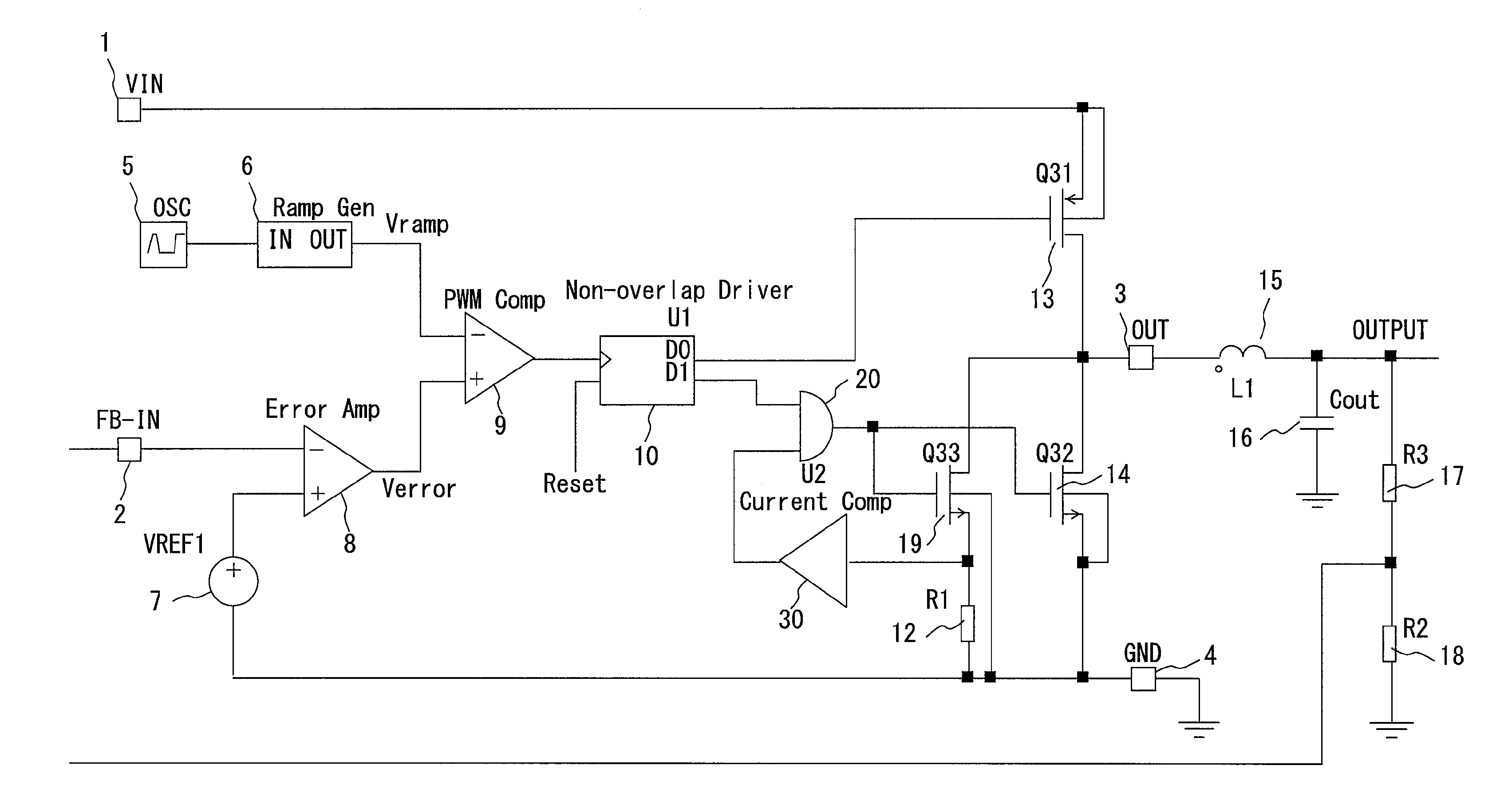
[0048]FIG. 3 shows a configuration of the abnormal current preventive circuit and the synchronous rectification buck type DC-DC converter including the circuit according to an embodiment of the present invention. In FIG. 3, the configuration includes: an input power source terminal (VIN terminal) 1; a feedback voltage input terminal (FB-IN terminal) 2 to which a feedback voltage detected after dividing an output voltage (OUTPUT) supplied to a load not shown in FIG. 3 by a resistor R3 (17) and a resistor R2 (18) is input; an output terminal (OUT terminal) 3 of a circuit for controlling energy accumulation / release (hereinafter energy accumulation is referred to as ‘charge’, and energy release as ‘discharge’); a ground terminal (GND terminal) 4; an oscillator (OSC) 5 for outputting a clock signal; a ramp generator 6 for generating a ramp signal Vramp by a trigger of the output of the oscillator (OSC) 5; an error amp 8 for comparing a feedback voltage with a reference voltage VREF1 (7) ...

embodiment 2

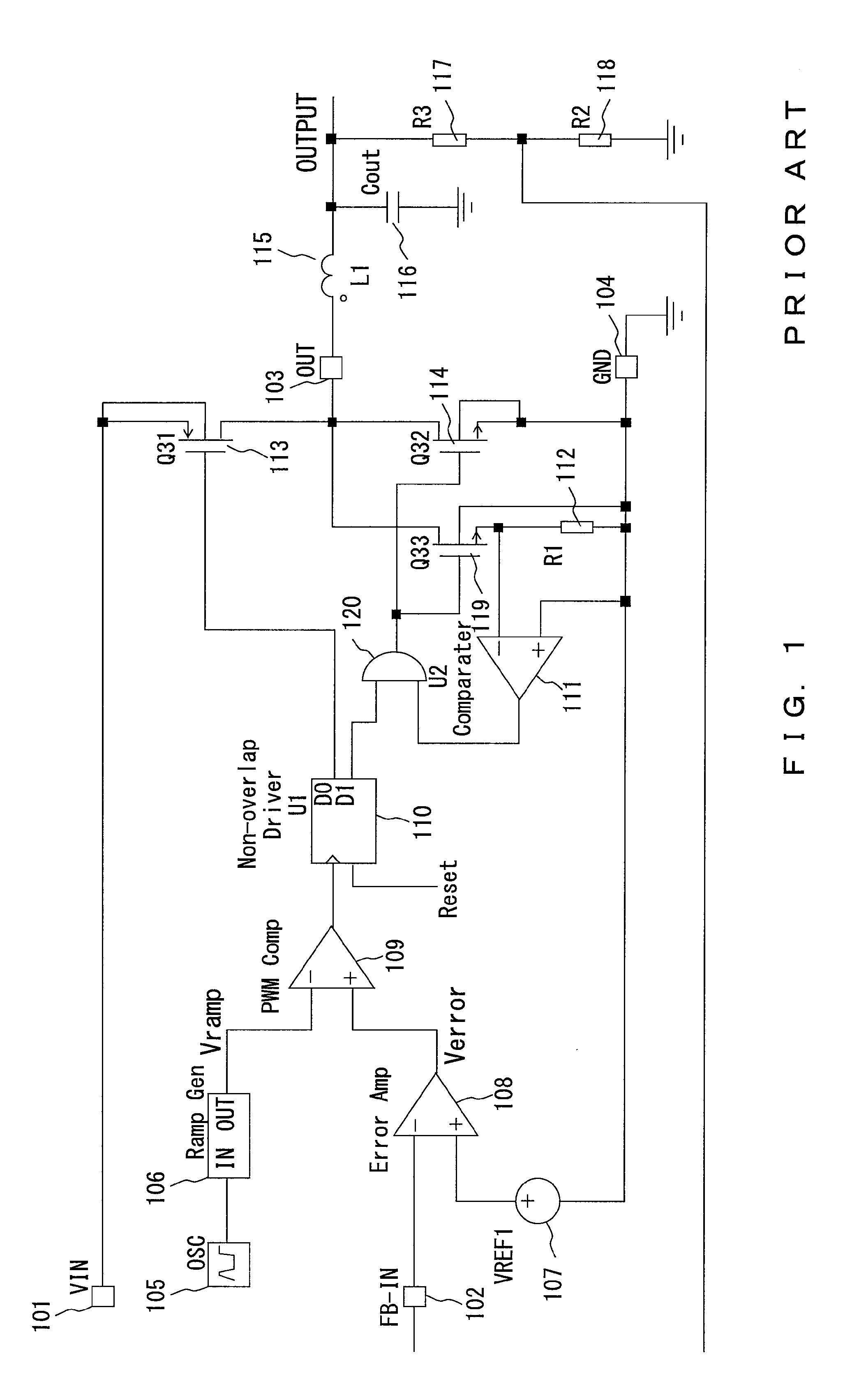
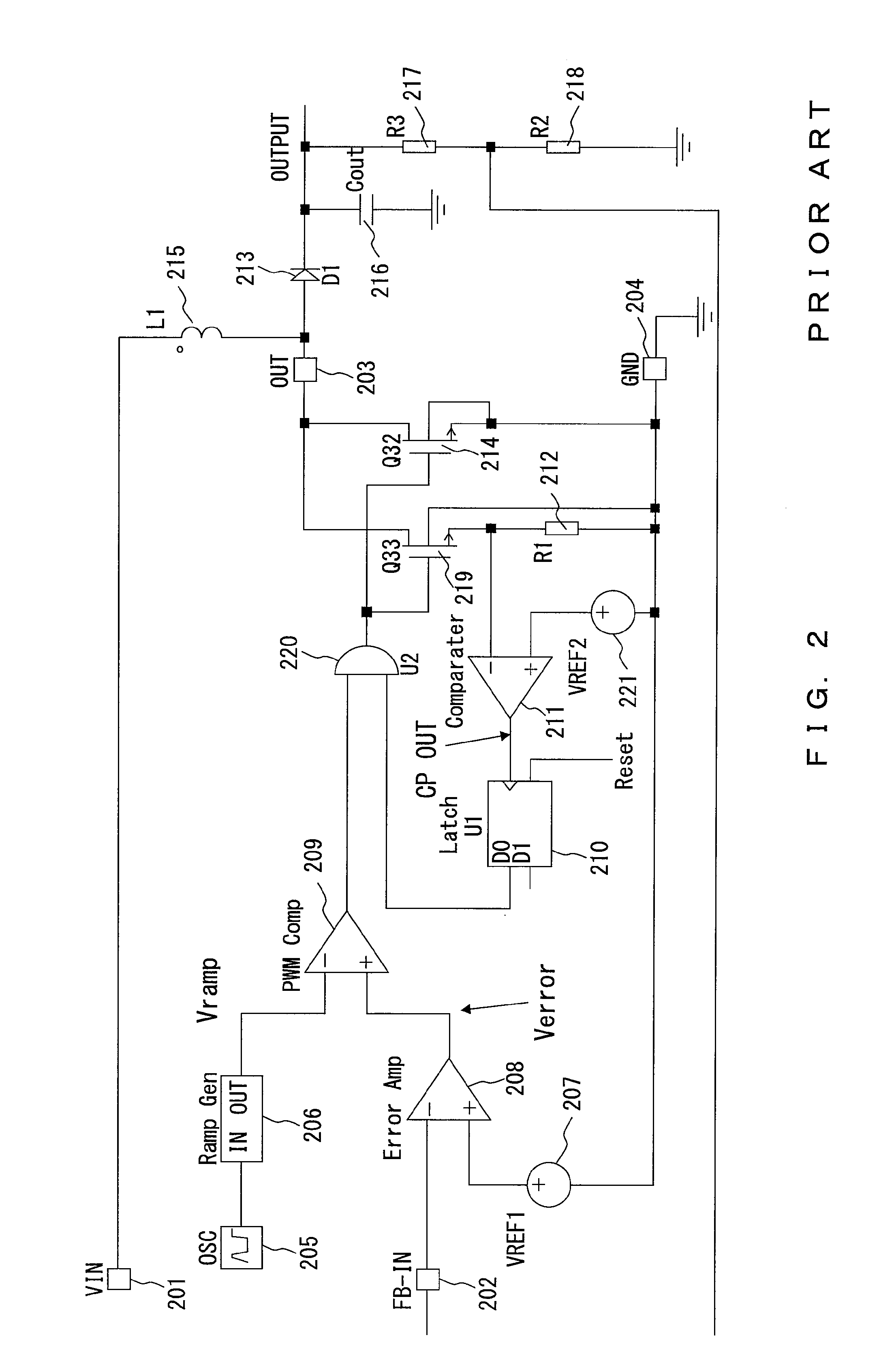
[0075]The description above is prepared for the embodiment of the countercurrent preventive circuit in a buck type DC-DC converter, but a current comparator similar to the circuit described above for the embodiment can be applied to the overcurrent preventive circuit of the boost type DC-DC converter shown in FIG. 15. That is, FIG. 15 shows an example of the embodiment of the overcurrent preventive circuit in a boost type DC-DC converter. In the embodiment, the voltage comparator 211 in the conventional overcurrent preventive circuit shown in FIG. 2 for determining the presence / absence of an overcurrent by comparing the voltage of the detection resistor R1 (212) with the reference voltage VREF2 (221) is replaced with the current comparator 30 for determining the presence / absence of an overcurrent by comparing the current flowing through the current detection resistor R1 (12) with a predetermined reference current. When an overcurrent is detected using the current comparator 30, the ...

embodiment 3

[0076]FIG. 16 shows an embodiment of the overcurrent preventive circuit in a buck type DC-DC converter. Since a high-side switching device (Q31) 14′ to be checked for an overcurrent is connected to the power source 1, an abnormal current (overcurrent) detection resistor R4 (12′) is also connected between the source of a switching device (Q34) 19′ and the power source 1. The switching device (Q31) 14′ and the switching device (Q34) 19′ are configured by a Pch MOSFET unlike the switching devices Q32 and Q33 shown in FIG. 3. Therefore, the position of the input terminal of the current comparator 30 is different from that of the current comparator of the boost type DC-DC converter, and is changed to the connection point of the abnormal current (overcurrent) detection resistor R4 (12′) and the source of the switching device (Q34) 19′.

[0077]FIG. 17 shows a configuration of a current comparator used in preventing an overcurrent of the buck type DC-DC converter. In FIG. 17, the configuratio...


PUM


Abstract

The voltage of a detection resistor connected to the drain of a low-side switching device is normally a negative voltage, but a positive voltage appears when a countercurrent occurs in an abnormal state. A current comparator monitors the voltage of the detection resistor, transmits high output to an AND circuit whole the voltage of the detection resistor is a negative voltage to maintain the output voltage of the current comparator in a low state when an output signal of a driver can be transmitted to the low-side switching device, and allows the output voltage of the current comparator in a low state when the voltage of the detection resistor becomes a positive voltage, thereby forcibly turning off the low-side switching device.

Description

BACKGROUND OF THE INVENTION[0001]1. Field of the Invention[0002]The present invention relates to an abnormal current preventive circuit of a DC-DC converter for determining the presence / absence of an abnormal current such as a countercurrent from an energy-accumulated inductor, an overcurrent of an inductor, etc., and preventing the abnormal current when it is detected.[0003]2. Description of the Related Art[0004]FIG. 1 shows a configuration of a synchronous rectification buck type DC-DC converter which determines the presence / absence of a countercurrent as an abnormal current, and includes a conventional countercurrent preventive circuit for preventing the countercurrent when it is detected. In FIG. 1, the configuration includes: an input power source terminal (VIN terminal) 101; a feedback voltage input terminal (FB-IN terminal) 102 to which a feedback voltage detected after dividing an output voltage (OUTPUT) supplied to a load not shown in FIG. 1 by a resistor R3 (117) and a res...

Claims


Application Information

Patent Timeline
Patent Type & Authority Applications(United States)
IPC IPC(8): H02H7/00H03K5/153
CPCH02M1/32Y02B70/1466H02M3/1588Y02B70/10
Inventor NAKAHASHI, YASUNORIYAMADAYA, MASAYUKIYAMANE, SATOSHI
Owner FUJI ELECTRIC CO LTD
Why Eureka
Try Eureka