[0196]Thus, it can be desirable that the time diagram representing ΔPcomp(t) must look as purely
rectangular pulse having the desirable amplitude P0 and algorithmically determined duration Tc=tend−tst which is understood hereinafter as the time interval between said starting and ending signals. However, it can be appreciated that in real devices the shape of actual diagram ΔPcomp(t) may differ significantly from ideal one. Two diagrams shown in the top of FIG. 17 represent more realistic examples of two independent cycles ΔPcomp(t) having different amplitudes P0(a) and P0(b) notwithstanding their quasi-rectangular shape is close to ideal expectations. An
advantage of the present invention is that precision of the fluid delivery can be maintained in the face of even substantial variations of real diagrams ΔPcomp(t) related to different cycles. Thus, a mechanism of the compressing
system 14 can be made simple without the need for high precision parts. For example, the amplitude P0 produced in different cycles may be up to five times more and / or up to five times less than its average value expected by a preprogrammed processor. In other words, the bracket ratio Pmax / Pmin can be as high as about 25. Moreover, some embodiments can work properly even if the elevated
plateau of the pressure pulse is not quite stable and can change during Tc up to about 70% of P0 or even more (see top view of FIG. 18 for example). Discussed later “smart” algorithms related to the method of present invention are capable of compensating very strong variations of the shape of ΔPcomp(t).
[0197]It can be appreciated that due to “soft” technical requirements the mechanism of the
compression system 14 of the invention may be simpler and less precise than complicated high precision mechanisms of known devices of the prior art. However, actual behavior of the
system 14 desirably satisfies at least certain minimum requirements related to average Tc. It may be desirable that average interval Tc exceeds at least about two times the typical time Tup of fast transition from initial level ΔPcomp (0)=0 to the highest pressure achieved in the compression section 8 during Tc. It can be desirable that average Tc exceeds Tup at least about ten times, and it can be desirable that average Tc exceeds Tup by about fifty times or more. For example, if the
average duration Tc of the dosing cycle is chosen to be about 20 s then a desirable
transition time Tup can be not longer than 0.4 s, and alternatively, not exceed 10 s.
[0198]It may also be desirable that after the ending
signal is sent by the
control system, a rapid pressure drop occurs in the compression section 8 of the reservoir 1 during as short time Tdown as the first
transition time Tup discussed above. The examples depicting both transition times Tup and Tdown are provided in FIG. 17 and FIG. 18.
[0199]Multiple different executive mechanisms of the
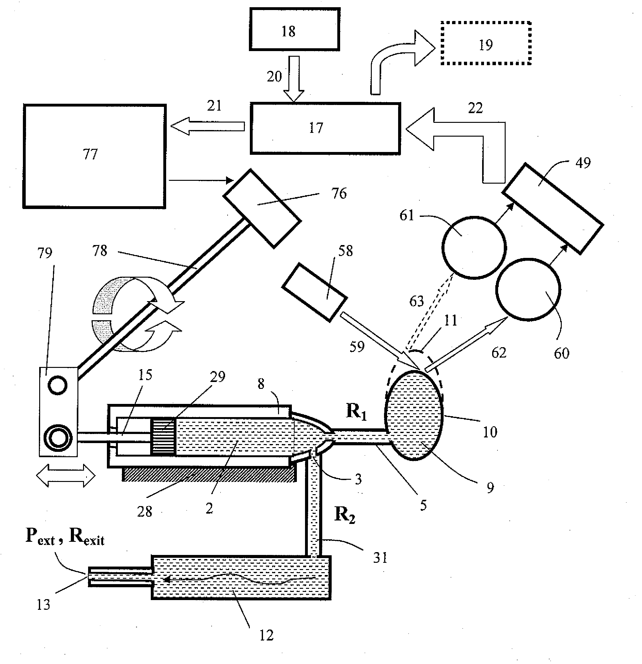
system 14 can be used to fulfill simple technical conditions disclosed above. FIG. 19 represents schematically an example of a simple device of the invention wherein the compressing mechanism of the system 14 exploits traditional
syringe shown also in FIG. 5. In order to change the squeezing-out force over time, this kind of compressing system comprises
piston 29 inserted into the
syringe's body 8, and an electromechanical system capable of moving said
piston in either of two opposite directions according to two control signals 21 sent by the processor. Also, this mechanism comprises block 76 combining the electric step-motor with the mechanical
reducer. The motor is connected with standard power supply 77 causing the step-motor to make a programmatically determined number of angular steps in any direction, whether
clockwise or counterclockwise (see thick round arrows), according to either starting or ending signals of the processor 17. The rotating driving shaft 78 of the
reducer is combined with the lever 79 in order to transform this rotation into back-and-forth movement (shown with thick double directed arrow) of the
piston rod 15. In this example it is desirable that the
syringe's body 8, the piston 29, and all
moving parts of the system 14 are made of hard materials. At the same time all elastic properties of the syringe-like reservoir shown in FIG. 19 are fully concentrated in its indicator section 9.
[0200]A typical cycle of a syringe-like compressing system 14 shown in FIG. 19 is described below. A first starting
signal sent by the processor 17 causes the step-motor to make programmatically predetermined number Mup of steps. Correspondingly, the counterclockwise rotation of the driving shaft 78 makes the piston 29 to slide predetermined distance Δl in the right direction. This first movement takes a short time Tup, for example about 0.2 s, and then the step-motor stops to conserve the battery.
Piston 29 applies the compressing force only to the limited surface area Spist of the fluid 2 located inside the syringe 8 and causes sharp increase of fluid's pressure ΔPcomp(t). It can be desirable that the volume ΔV expelled by the piston's
relocation exceeds the preprogrammed fluid
dose D0 of current delivery cycle by the
order of magnitude, for example about 20 times. It may be obvious for those skilled in the art that the process of expelling may be accompanied by certain expansion of both elastic ring 29a and the body of the syringe 8 made of hard material. It is desirable also that simple devices satisfy the condition R2>>R1 as shown in FIG. 5. Due to the
transition time Tup being short, and the flow passage 12 comprising substantial non
zero resistance R2, the
fluid volume ΔV expelled by the piston cannot leave from exit opening 13 immediately. Instead, due to a relatively low R1 this volume is moved quickly from the section 8 made of hard material to expandable section 9. FIG. 19 shows how the initial shape of the elastic element 10 gets its expanded shape 11 in the process of a rapid
pressure increase in the indicator. It can be appreciated that the fluid's volume ΔV expelled by the piston into expandable indicator section 9 during the short transition time Tup can be expressed as: ΔVind=Spist Δl. In the case of a simple device supplied with the syringe-
type system 14, the amplitude P0 of jump-like
pressure increase is practically the same in both the compression and the indicator sections of the reservoir 1. In accordance with the equation (4) it obeys the following expression:P0=αSpistΔl (Eq.8)
[0201]Both the resistance R2 and actual pressure P0 measured by the
sensor system during each cycle are known to the processor, which calculates both the real magnitude of the fluid flow and right cycle duration Tc corresponding to the desirable
dose. When the proper Tc is reached and desirable dose D0 is obtained, the processor sends the ending
signal to the power supply block 77 of the system 14. After that the step-motor 76 makes predetermined number Mdown of back steps, rotates the driving shaft 78
clockwise and makes the piston 29 to slide back in the
left direction. This takes short time Tdown only and results in fast decrease of squeezing-out pressure in the reservoir as shown in top view of FIG. 17. It should be appreciated that typically the numbers of motor's steps are to be chosen in accordance with simple condition Mup>Mdown, providing an effective way of controlling the piston's actions.


