This helps you quickly interpret patents by identifying the three key elements:
Problems solved by technology
Method used
Benefits of technology
Benefits of technology
[0052]According to the first and seventh aspects of the present invention, mercury and other heavy metals in the exhaust gas can be reduced in the case of combusting high sulfur content coal.
[0053]According to the second and eighth aspects of the present invention, mercury and other heavy metals in the exhaust gas can be reduced by almost 99% with respect to the concentration at the boiler exit.
[0054]According to the third and ninth aspects of the present invention, in addition to the effects of the first and seventh aspects of the present invention, the exhaust gas temperature can be adjusted readily within the same exhaust gas system because the exhaust gas temperature at the exit of the heat recovery unit 11 is adjusted according to at least one among the amount of circulation of the heating medium between the heat recovery unit 11 and the reheater 13, connected by the circulation line 15 through which the heating medium flows, or the cooler (heater for water) 25, cooling the heating medium supplied from the heat recovery unit 11, the heating medium heating amount, and the heating medium cooling amount.
[0055]According to the fourth aspect of the present invention, in addition to the effects of the first asp
Problems solved by technology
Although the nitrogen oxides are removed by NOx removal equipment and the sulfur oxides are removed by a desulfurizer, mercury, selenium, cadmium, chromium, lead, zinc, and other heavy metals cannot be removed by the NOx removal equipment or desulfurizer and cannot be trapped completely by a precipitator for removing soot / dust in the exhaust gas.
Because these heavy metals are high in toxicity, emission restrictions thereof have recently become stricter.
Method used
Image
Click on the blue label to locate the original text in one second.
Reading with bidirectional positioning of images and text.
Examples
embodiment 1
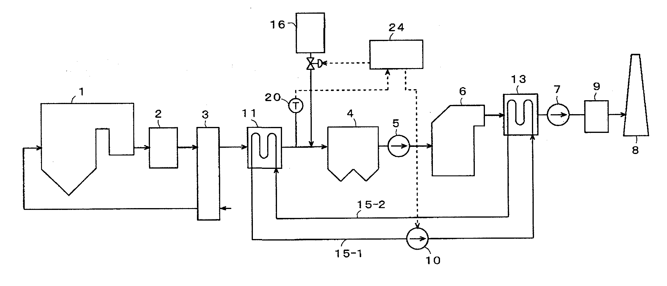
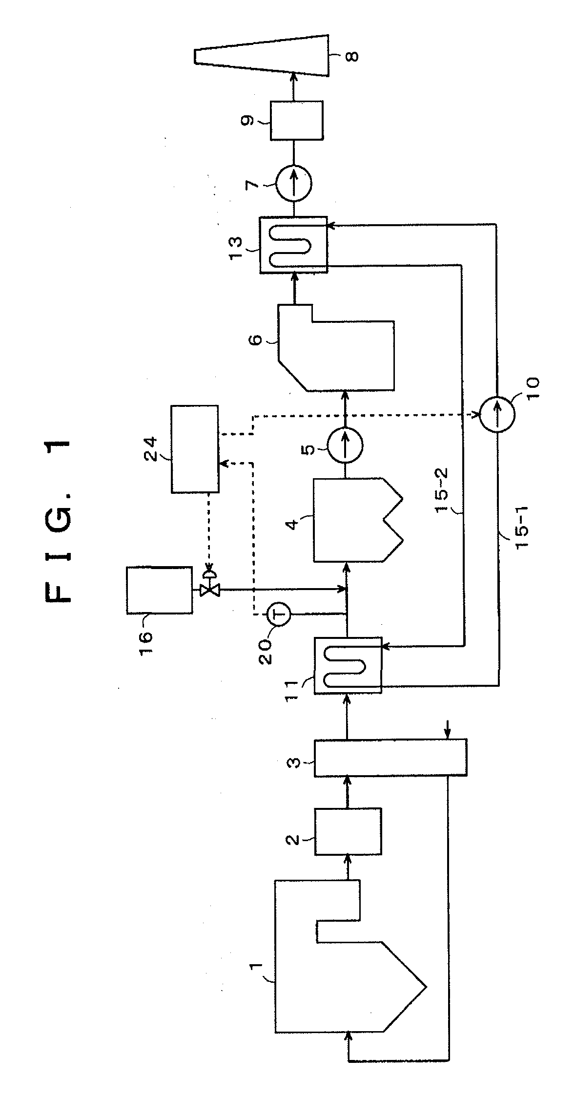
[0059]FIG. 1 is a block diagram of an exhaust gas treating system of an embodiment. Concentrations of exhaust gas components discharged from a boiler used in the embodiment according to the present invention are: a soot / dust concentration of 20 g / m3N; a NOx concentration of 200 ppm; a SOx concentration of 4000 ppm; and an Hg concentration of 10 μg / m3N.
[0060]With the exhaust gas treating system of the present embodiment shown in FIG. 1, an exhaust gas discharged from the boiler 1 is introduced into NOx removal equipment 2, and, after elimination of nitrogen oxides in the exhaust gas to not more than 20 ppm by a denitration catalyst, etc., inside the NOx removal equipment 2, the exhaust gas is introduced into an air preheater 3. The exhaust gas introduced into the air preheater 3 undergoes heat exchange with a combustion air that is supplied to the boiler 1 and, upon being cooled, for example, to 120 to 170° C., the exhaust gas is introduced into a heat recovery unit 11. Heat of the e...
embodiment 2
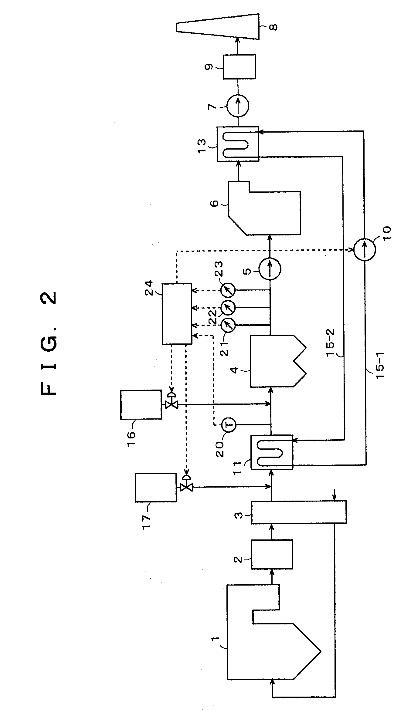
[0073]An embodiment shown in FIG. 2 is an exhaust gas treating system with which a configuration for adding an alkali is added to the exhaust gas treating system shown in FIG. 1 and furthermore with which at least one among an SO3 concentration meter 21, measuring the SO3 concentration in the exit exhaust gas of the dry electrostatic precipitator 4, a hydrogenchloride concentration meter 22, measuring a hydrogenchloride concentration, and a heavy metal concentration meter 23, measuring a heavy metal concentration, is disposed.
[0074]With the configuration shown in FIG. 2, the boiler 1, the NOx removal equipment 2, the air preheater 3, the heat recovery unit 11, the induction fan 5, the wet desulfurizer 6, the reheater 13, the desulfurization fan 7, the measurement unit 9, the chimney 8, the pump 10, the heating medium circulating ducts 15-1 and 15-2, the mercury adsorbent supply unit 16, the thermometer 20 at the heat recovery unit exit, and the controller 24 are the same as those ...
embodiment 3
[0089]An embodiment shown in FIG. 3 is a block diagram of an exhaust gas treating system, with which the mercury adsorbent supply unit 16 of the exhaust gas treating system shown in FIG. 1 is disposed not at the front stage portion of the electrostatic precipitator 4 but at an intermediate position of the electrostatic precipitator 4.
[0090]Besides the mercury adsorbent supply unit 16 and the electrostatic precipitator 4, the configuration shown in FIG. 3 has the same boiler 1, NOx removal equipment 2, air preheater 3, heat recovery unit 11, induction fan 5, wet desulfurizer 6, reheater 13, desulfurization fan 7, measurement unit 9, chimney 8, pump 10, heating medium circulating ducts 15-1 and 15-2, the mercury adsorbent supply unit 16, thermometer 20 at the heat recovery unit exit, and controller 24 as those of Embodiment 1 and description thereof shall be omitted.
[0091]Although not illustrated, control of the exhaust gas temperature by the heating medium flow rate in the heating me...
PUM
Property
Measurement
Unit
Time
aaaaa
aaaaa
Temperature
aaaaa
aaaaa
Concentration
aaaaa
aaaaa
Abstract
After adjusting an exhaust gas temperature at an exit of a heat recovery unit (11) of an exhaust gas treating apparatus to not more than a dew point temperature of sulfurtrioxide (SO3), a heavy metal adsorbent is supplied from a heavy metal adsorbent supply unit (16) disposed in an exhaust gas at an entrance of a precipitator (4) or an intermediate position within the precipitator (4), and the exhaust gas containing the heavy metal adsorbent is supplied into the precipitator (4). Preferably at this stage, the heavy metal adsorbent is supplied into the exhaust gas at the entrance of the precipitator (4) 0.1 seconds after the exhaust gas temperature at the exit of the heat recovery unit (11) has been adjusted to not more than the dew point temperature of SO3. Further preferably, in order to prevent acid corrosion of equipment, the heavy metal adsorbent is supplied after spraying an alkali into the exhaust gas at the entrance or exit of the heat recovery unit (11) and adjusting the exhaust gas temperature at the exit of the heat recovery unit to not more than the dew point temperature of SO3. Accordingly, even when coal with a high sulfur content is used as fuel, heavy metals in the exhaust gas can be removed effectively.
Description
TECHNICAL FIELD[0001]The present invention relates to an exhaust gas treating method and apparatus and particularly relates to an apparatus and a method, which are for reducing trace component concentrations in an exhaust gas discharged from a chimney and with which trace component removal performance in a dry precipitator is improved to remove trace heavy metal components in the exhaust gas.BACKGROUND ART[0002]Mercury and other heavy metals are contained in addition to nitrogen oxides and sulfur oxides in an exhaust gas discharged from a thermal power plant boiler, etc., which is a combustion apparatus that uses coal or other fossil fuel. Although the nitrogen oxides are removed by NOx removal equipment and the sulfur oxides are removed by a desulfurizer, mercury, selenium, cadmium, chromium, lead, zinc, and other heavy metals cannot be removed by the NOx removal equipment or desulfurizer and cannot be trapped completely by a precipitator for removing soot / dust in the exhaust gas. ...
Claims
Application Information
Patent Timeline
Application Date:The date an application was filed.
Publication Date:The date a patent or application was officially published.
First Publication Date:The earliest publication date of a patent with the same application number.
Issue Date:Publication date of the patent grant document.
PCT Entry Date:The Entry date of PCT National Phase.
Estimated Expiry Date:The statutory expiry date of a patent right according to the Patent Law, and it is the longest term of protection that the patent right can achieve without the termination of the patent right due to other reasons(Term extension factor has been taken into account ).
Invalid Date:Actual expiry date is based on effective date or publication date of legal transaction data of invalid patent.

