
Biomaterial, method of constructing the same and use thereof

a biomaterial and biomaterial technology, applied in the field of porous biomaterials, can solve the problems of poor mechanical match between bone at the site of implantation and surrounding bone as part of the skeleton, loss of bone mass in surrounding bones and joints, and destruction of cartilage, etc., and achieve the effect of reasonable cost and simplified orientation

Inactive Publication Date: 2010-03-25
INAGAKI MASAHIKO +2
View PDF7 Cites 40 Cited by
  • Summary
  • Abstract
  • Description
  • Claims
  • Application Information

AI Technical Summary

Benefits of technology

[0048]The present invention relates to a biomaterial which, by having formed in at least some portion thereof a porous region of controlled orientation, increases infiltration by living tissue and the like, and is thus a material that increases the ability for essential bodily functions to appear at the site of implantation. The inventive biomaterial is characterized (1) in that the porous region has a group of oriented pores of controlled size and shape, enabling infiltration by living tissue and the introduction of cells, (2) in that connecting pores which link together the oriented pores and allow the passage of bodily fluids and gas bubbles have been formed therein, and (3) by being formed in a manner where the oriented pores are spatially configured so as not to be directly connected to other oriented pores and the connecting pores which link together the oriented pores are spatially configured so as not to be directly connected to other connecting pores.
[0089](6) Through control of the geometric shape—such as the shape and orientation—of the pores and control of the pore distribution, anisotropy arises in the attenuation of sound waves, vibrations and electromagnetic waves by the porous body, making it possible to achieve the necessary absorption of vibrations and electromagnetic waves at the site of implantation.

Problems solved by technology

However, because such artificial bones have mechanical characteristics (e.g., Young's modulus) which differ considerably from those of living bone, a good mechanical match with bone at the site of implantation and with surrounding bone connected thereto as part of the skeleton has not been achieved.
This gives rise to problems such as the destruction of cartilage and the loss of bone mass in surrounding bones and joints due to stress concentration.
Also, in artificial bone, when the pores at the interior are isolated, this impedes the passage of bodily fluids, etc., restricting the supply of nutrients and oxygen.
As a result, the infiltration by bone and other tissue is inadequate, hindering tissue regeneration.
Also, when gas bubbles that have nowhere to go remain within the pores, they can hamper cellular, tissue and vascular infiltration.
However, in these reports, the only artificial objects serving as scaffolding that are mentioned are very small honeycomb shaped bodies or thin sheets in which perforations have been formed.
Because the formation of open pores is probabilistic, it is impossible to directly control the orientation, size and shape of the pores.
Also, probabilistically, there is a possibility that closed pores will form.
The existence of closed pores presents a danger of gas bubbles being released within the body should breakage of the biomaterial occur.
Moreover, the inability of bodily fluids, cell culture fluids, cells and tissue to infiltrate closed pores limits the utility of such porous bodies in tissue repair, tissue engineering and regenerative medicine.
Hence, such processes are unsuitable as methods for manufacturing biomaterials.
However, in a honeycomb-like arrangement of communicating pores, each pore is independent, which is undesirable for bone tissue infiltration.
Moreover, a porous body without orientation is poorly suited for controlling the morphology of the living tissue that is to be formed there.
However, given that the size of the ice which forms during freezing and which has grown so as to be macroscopically oriented determines the size and shape of the pores, while some control of the size of the pores by the ice growth conditions is possible, a porous body in which the shape and size have been completely controlled cannot be formed.
However, because the columnar cells are stacked so as to have different directions of orientation, one problem is that bi-directional throughholes are inevitably formed.
Another problem is that, in the process of forming a porous body in which throughholes have been formed, the direction having a relatively good strength to loading becomes fixed in a direction perpendicular to the direction of the throughholes.
Yet another problem is that, owing to constraints having to do with the production steps, this process can only be applied to low-temperature curing calcium phosphate shaped bodies.
Also, the fact that the oriented throughholes are in mutual contact and directly connected with each other does not lend itself well to control of the spatial configuration of the oriented holes, resulting in the additional problem that the shape of the holes in the areas of contact cannot be controlled.
However, in such a method of forming a porous body, all that can be obtained is a structure in which the oriented pores are scattered within a network of pores formed in the gaps between the very small spherical units; also, the spatial size of the main pores formed is limited by the size of the units.
Also, because the gaps between the units invariably become connecting pores, another problem is the formation of unnecessary connecting pores.
This type of approach is thus inconvenient in the design of, for example, strength, mechanical characteristics, control of the propagation of vibrations, and optical properties.
In addition, when spherical units are brought together, because the units join together at the points where spheres come into contact with other spheres, forming a porous body having a high strength is difficult.

Method used


Image

  • Biomaterial, method of constructing the same and use thereof
  • Biomaterial, method of constructing the same and use thereof
  • Biomaterial, method of constructing the same and use thereof

Examples


example 1

Stacking of Titanium Sheets

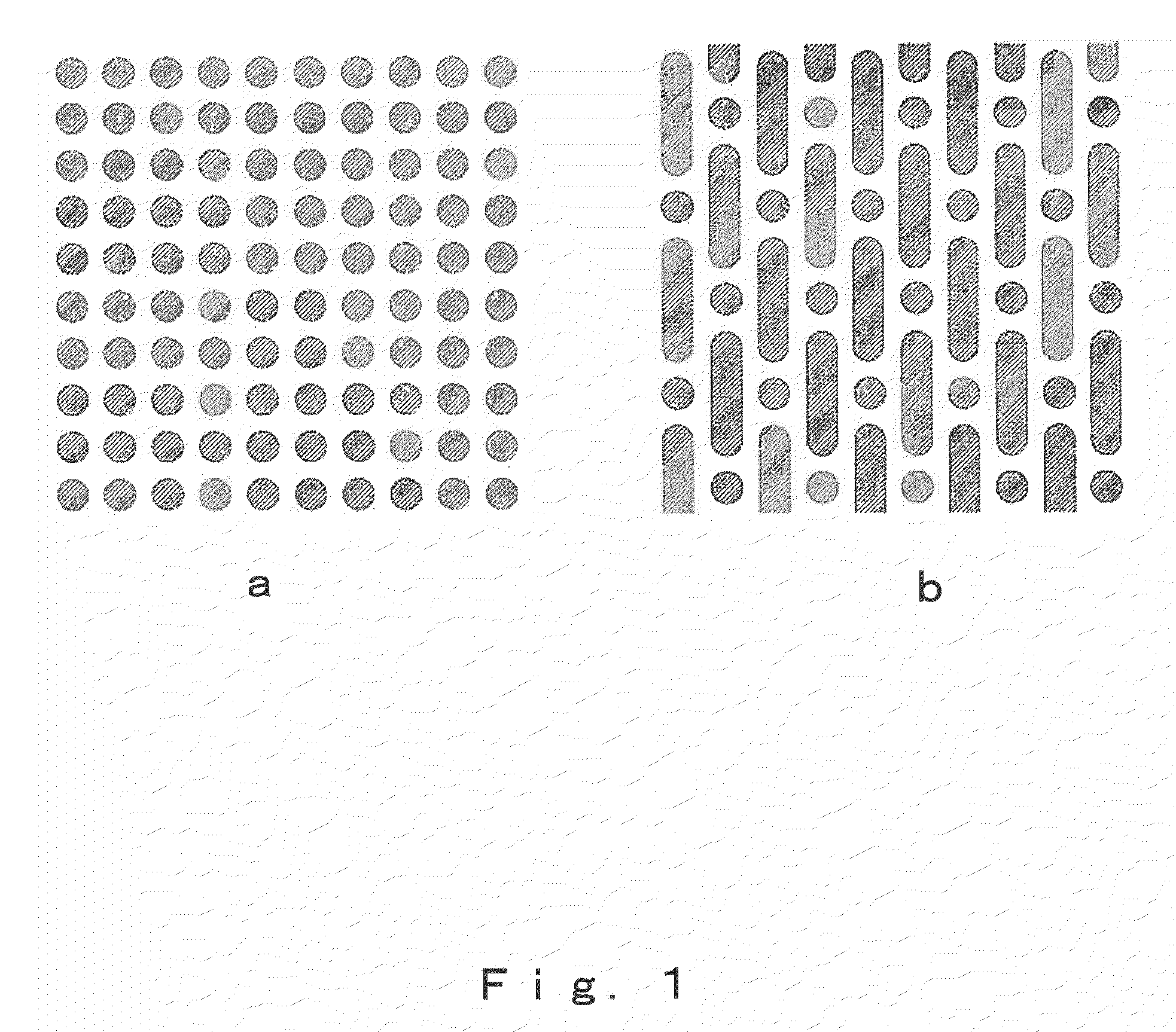
[0108]Three 100 μm thick titanium sheets having circular throughholes of 150 μm radius (shape: FIG. 1a) and three 100 μm thick titanium sheets having circular holes of 150 μm radius and throughholes of 300 μm width and 1,200 μm length (shape: FIG. 1b) were alternately stacked, and the titanium sheets were diffusion bonded to each other by heating in a vacuum at from 500 to 1,500° C. for a period of from 1 to 500 minutes while applying a pressure of from 10 to 500 kg / cm2.

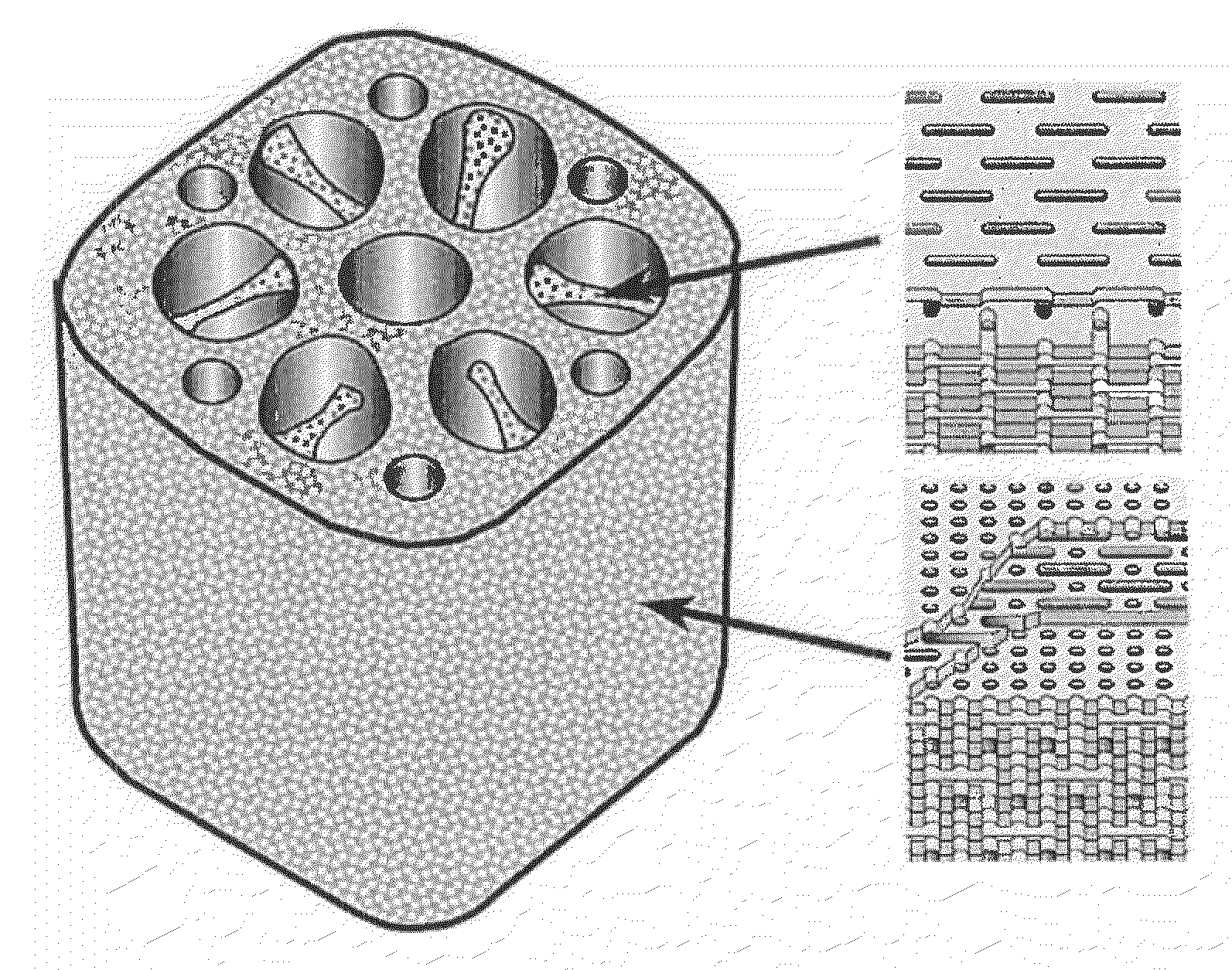
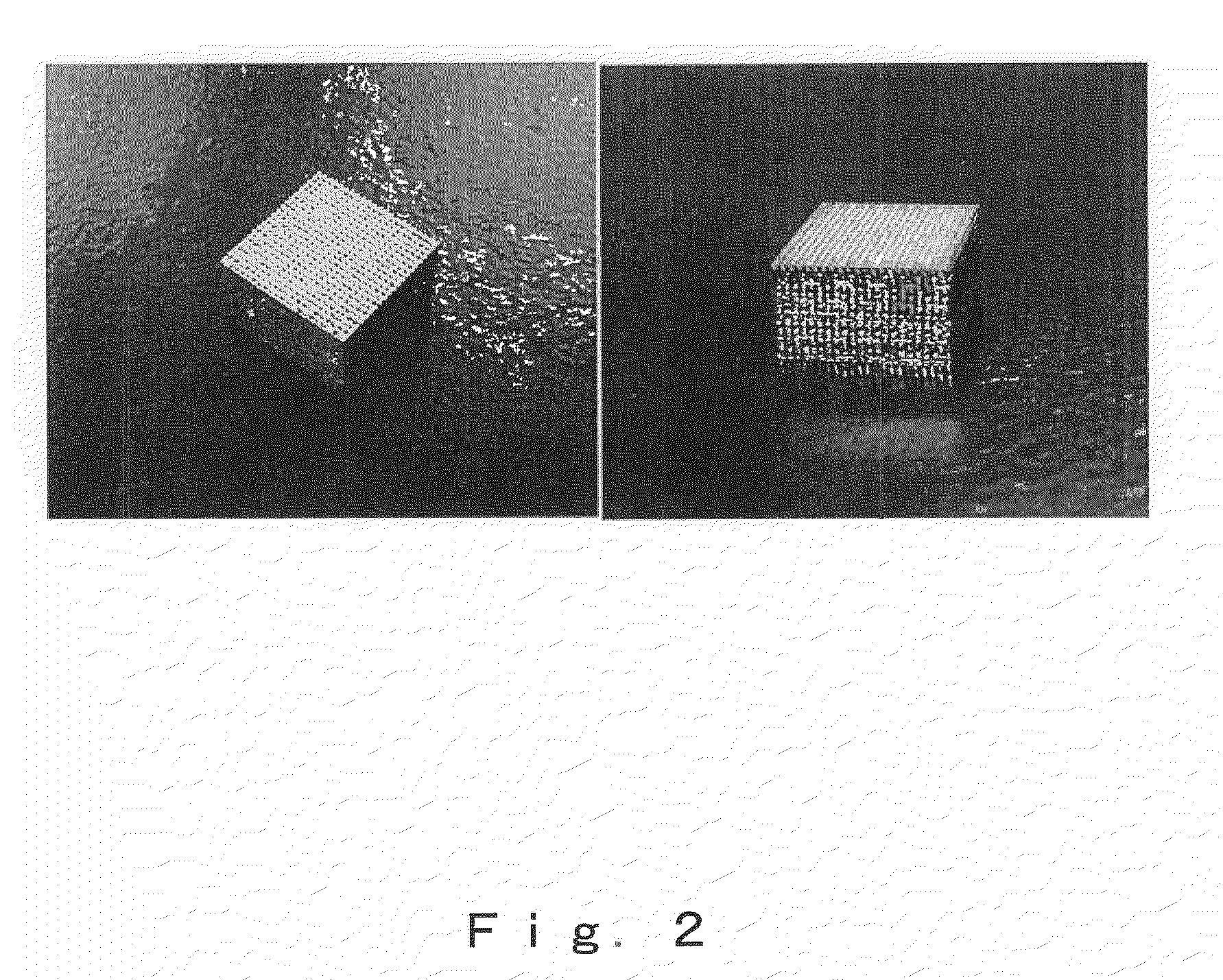
[0109]This gave a bulk porous body made of titanium characterized by being a porous body having therein a group of oriented pores of individually controlled size, shape and direction and with an orientation in one direction and also having formed therein connecting pores that link together the oriented pores and enable the passage of bodily fluids and gas bubbles, and by being formed with a controlled spatial configuration of the oriented pores and connecting pores (FIGS. 2 and 3). It was p...

example 2

Stacking of Polylactic Acid Sheets

[0110]A 300 μm thick polylactic acid sheet having circular throughholes of 150 μm radius (shape: FIG. 1a) and a 300 μm thick polylactic acid sheet having circular holes of 150 μm radius and throughholes of 300 μm width and 1,200 μm length (shape: FIG. 1b) were stacked, and the polylactic acid sheets were fusion bonded to each other by heating in the open air at from 80 to 200° C. for a period of from 1 to 500 minutes while applying a pressure of from 0.1 to 10 kg / cm2.

[0111]This gave a bulk porous body made of polylactic acid characterized by being a porous body having therein a group of oriented pores of individually controlled size, shape and direction and with an orientation in one direction and also having formed therein connecting pores that link together the oriented pores and enable the passage of bodily fluids and gas bubbles, and by being formed with a controlled spatial configuration of the oriented pores and connecting pores. It was possib...

example 3

Stacking of Polylactic Acid Sheet and Titanium Sheet

[0112]A 100 μm thick titanium sheet having circular throughholes of 150 μm radius (shape: FIG. 1a) and a 300 μm thick polylactic acid sheet having circular holes of 150 μm radius and throughholes of 300 μm width and 1,200 μm length (shape: FIG. 1b) were stacked, and the sheets were fusion bonded by heating in the open air at from 80 to 200° C. for a period of from 1 to 500 minutes while applying a pressure of from 0.1 to 10 kg / cm2. This gave a bulk porous body made of polylactic acid and titanium that was characterized by being a porous body having therein a group of oriented pores of individually controlled size, shape and direction and with an orientation in one direction and also having formed therein connecting pores that link together the oriented pores and enable the passage of bodily fluids and gas bubbles, and by being formed with a controlled spatial configuration of the oriented pores and connecting pores.


PUM

PropertyMeasurementUnit
Lengthaaaaaaaaaa
Lengthaaaaaaaaaa
Thicknessaaaaaaaaaa

Abstract

The present provides a biomaterial composed in part of a porous material having an internal structure that has been completely controlled so as to optimize living tissue infiltration or cell introduction, a method of manufacturing, and uses thereof, including bio-implant materials for artificial bones, artificial joints and artificial tooth roots, and cell culture supports; the biomaterial undergoes increased infiltration by living tissues and the like owing to the formation of a porous region in at least a portion of the material, wherein the porous region is a porous body having therein a group of oriented pores that has an orientation and is made up of pores whose size, shape and direction have been controlled to optimize living tissue infiltration or cell introduction, and also having formed therein connecting pores that link together the primary pores and enable the passage of bodily fluids and gas bubbles, and formed with a spatial configuration in which the oriented pores are not directly connected to other oriented pores and the connecting pores which link together the oriented pores are not directly connected to other connecting pores.

Description

TECHNICAL FIELD[0001]The present invention relates to a porous biomaterial and a method of manufacture thereof. More specifically, the invention relates to a bio-implant material, e.g., artificial bone, artificial joint, artificial tooth root, or cell culture support in which have been formed, at the interior of a porous body, connecting pores which are controlled for orientation, size and shape thereof, and to a method of manufacture thereof; and this bio-implant material or cell culture support is characterized by having formed, at the interior of a porous body, a group of oriented pores controlled for pore size, shape and direction thereof and connecting pores which link together the oriented pores. The present invention provides, in the technical field of biomaterials, a novel type of biomaterial, e.g., bio-implant material, cell culture support, dialysis component, circulation device component, or filter, which is a porous biomaterial having formed, at the interior thereof, por...

Claims


Application Information

Patent Timeline
IPC IPC(8): B32B3/26B29C41/42C12N5/00B29C33/42A61F2/02A61F2/28
CPCY10T428/2495A61L27/56Y10T428/249953Y10T428/249978
Inventor INAGAKI, MASAHIKOWATAZU, AKIRA
Owner INAGAKI MASAHIKO
Learn More