Method and apparatus for producing a constant air flow from a blower by sensing blower housing vacuum

a technology of constant air flow and blower, which is applied in the direction of instruments, heating types, static/dynamic balance measurement, etc., can solve the problems of increasing complexity and cost of prior art controllers to achieve coordination, and achieve constant air flow, constant air flow, and maximum combustion

Inactive Publication Date: 2010-03-25
RBC HORIZON
View PDF9 Cites 37 Cited by
  • Summary
  • Abstract
  • Description
  • Claims
  • Application Information

AI Technical Summary

Benefits of technology

[0004]In accordance with the principles of this invention, an airflow control system preferably comprises a blower motor, a vacuum or pressure differential sensor mounted to sense the vacuum created by the blower, and an embedded controller that receives as input a signal from the vacuum sensor and provides an output voltage to control the speed of the blower motor to maintain a specific vacuum and thereby a constant air flow. Thus, the present invention uses the direct measurement of the air flow by way of the sensed vacuum within the blower housing to monitor and control the blower speed and maintain a constant air flow, or otherwise control the air flow to maximize combustion. This allows the blower to be designed as part of an HVAC system without regard to variations in installation that would have to be taken into account with prior art designs, such as vent length, and also provides reliable and efficient operation regardless of temporary conditions such as blockages in the vent. The present invention is also elegantly simpler in design and thus less expensive, having fewer components and with less need to coordinate its operation with other system components in order to achieve true constant, or controlled, air flow. In the HVAC industry it is well known that variable speed ventilator blower operation leads to improved system efficiency and that constant airflow control combined with this variable speed control enhances HVAC operating parameters such as reduced flue operating temperatures, more uniform control of CO2, lower operating noise, insensitivity to vent lengths in draft inducers, and better climate control in ventilation blower applications. Thus, the present invention also finds a ready application to the variable speed applications as well.
[0005]In a typical installation, this constant air flow blower is used as the combustion blower, supplying air for combustion of a supply gas within a gas furnace, or HVAC unit. By providing better and more reliable control of air flow to the burner, more efficient operation of the burner is achieved and hence more efficient furnace operation, resulting in savings to the consumer.
[0006]In accordance with the principles of this invention, an airflow control system preferably comprises a blower motor mounted to drive a blower wheel contained within a housing, a vacuum switch mounted to the housing to detect the negative pressure differential drawn by the blower wheel as it rotates within the housing, the vacuum switch generating a variable voltage for feedback to an electronic control, with the electronic control generating a control voltage to vary the blower motor speed as required to maintain a relatively constant negative pressure within the blower housing and thereby a relatively constant air flow from the blower. Should the vacuum sense a pressure outside its ordinary limits, the control may be connected to a gas supply valve which it would then shut off to interrupt furnace operation until the source of the problem could be found and corrected, in order to provide a safety feature that is directly tied to air flow in the burner pathway. Due to its more direct relationship, it is thought that this safety feature is more reliable than others, and hence provides a greater safety advantage.

Problems solved by technology

However, this type of airflow control requires coordination with other controllers in the overall HVAC system to achieve constant airflow as the actual airflow is typically affected by other parameters such as vent length, blockages in the vent, etc.
Thus, these prior art controllers suffer from the increased complexity and cost required to achieve this coordination, and further are typically designed to match a particular HVAC device and installation.

Method used


Image

  • Method and apparatus for producing a constant air flow from a blower by sensing blower housing vacuum
  • Method and apparatus for producing a constant air flow from a blower by sensing blower housing vacuum
  • Method and apparatus for producing a constant air flow from a blower by sensing blower housing vacuum

Examples


Embodiment Construction

[0021]In the following detailed description, numerous specific details are set forth in order to provide a thorough understanding of the inventors' best mode of the invention to one of ordinary skill in the art. However, it will be understood by those skilled in the art that the present invention may be practiced without these specific details. Instead, well-known methods, procedures, and components may be used with the present disclosure as a guide to produce other embodiments of the invention, by those of skill in the art, and all of those other embodiments are to be considered as included within the scope of this invention.

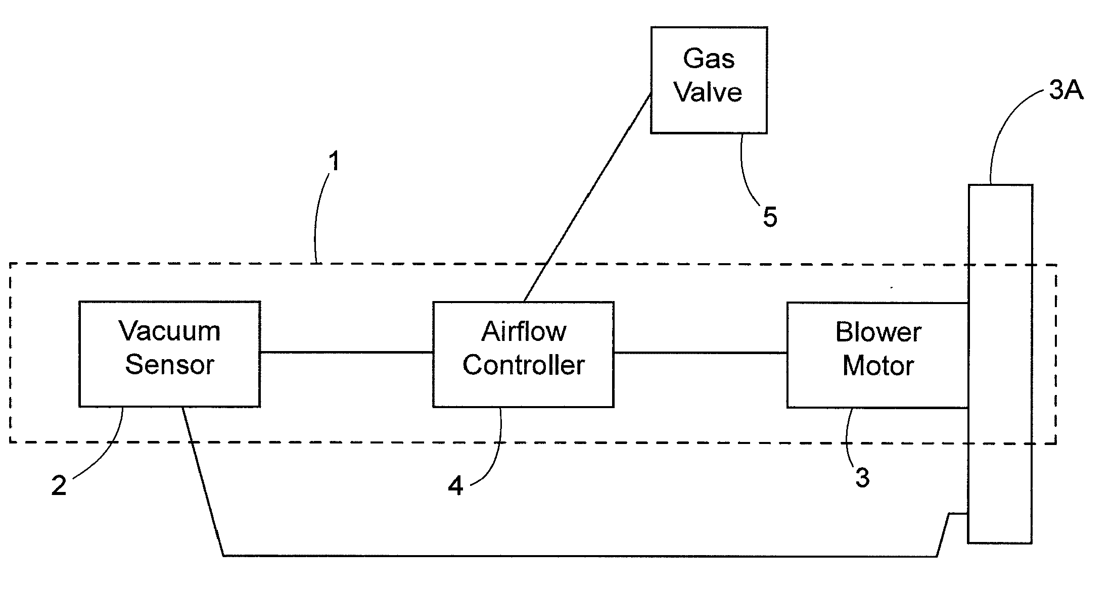
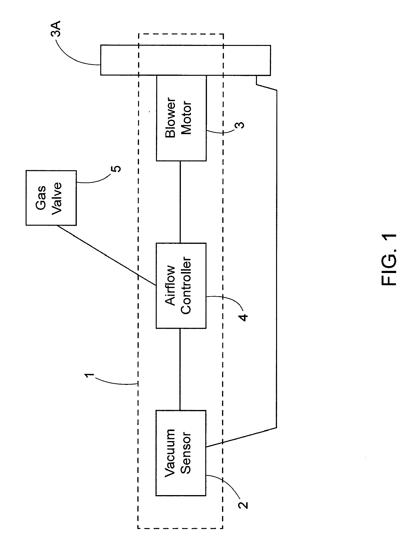
[0022]FIG. 1 illustrates a block diagram of the air flow control system 1 of the present invention. A vacuum (or pressure differential) sensor 2 senses the vacuum induced by a blower motor 3 within a blower housing 3A. An airflow controller 4 excites the vacuum sensor 2, extracts a suitable electronic feedback signal proportional to the sensed blower vacuum, an...


PUM


Abstract

An airflow control system for a blower providing the combustion air for an HVAC system comprises a single phase AC blower motor driving a blower wheel within a blower housing, a vacuum sensor mounted to the housing to sense the vacuum or pressure differential created by the blower as it operates, and a controller that receives as its only feedback signal a variable signal from the vacuum sensor which signal is proportional to the sensed vacuum within the housing and provides an output voltage to the blower motor to adjust the blower motor speed to thereby preferably produce a constant air flow.

Description

CROSS REFERENCE TO RELATED APPLICATION[0001]This application claims priority to provisional application Ser. No. 60 / 823,283 filed Aug. 23, 2006, the disclosure of which is incorporated herein by reference.TECHNICAL FIELD OF THE INVENTION[0002]The present invention relates to control of airflow, and particularly an improved controller utilizing a vacuum sensor (pressure differential sensor) to control the speed of a blower motor so that the airflow through the blower remains constant.BACKGROUND OF THE INVENTION[0003]In operation, an air blower creates an air pressure differential or “vacuum” within its housing. The amount of airflow created by the blower is directly proportional to this air pressure differential. Some HVAC blowers today use brushless DC motors and their derivatives. That's because a typical brushless DC motor exhibits a linear torque (and thus current) versus speed curve, thereby making it easy for controllers for these HVAC blowers to implement constant airflow cont...

Claims


Application Information

Patent Timeline
Patent Type & Authority Applications(United States)
IPC IPC(8): G05D23/19G05D7/06
CPCF04D27/004Y02B30/746F24F2011/0042F24F11/0079F24F2110/40F24F11/77Y02B30/70F24F2140/10
Inventor GATLEY, WILLIAM STUARTJONES, ROBERT E.
Owner RBC HORIZON
Why Eureka
Try Eureka