
Rotating Sunlight/Light Beam for Fractional/Beneficial Use.

a light beam and fractional technology, applied in the field of solar energy distribution systems, can solve the problems of large energy consumption, relatively unimportant conservation, and scarcity of energy producing fuels, and achieve the effect of reducing the amount of energy, easy and reasonably inexpensive construction

Active Publication Date: 2010-04-08
WALDEN JACK ONEAL
View PDF3 Cites 10 Cited by
  • Summary
  • Abstract
  • Description
  • Claims
  • Application Information

AI Technical Summary

Benefits of technology

[0007]It is therefore an object of the present invention to provide a Rotating Sunlight / Light Beam for Fractional / Beneficial Use (solar-light / man-made light, energy management system for reducing the amount of energy which is consumed by a plurality of lighting loads).
[0008]The solar-collector would typically be located on rooftops for the gathering of the Sun's rays white the man-made light collector would / may be located below roof level. Both units would have to be manufactured. While some could be sized to cover general and similar lighting loads others would, no doubt, have to be individually sized to the specified requirements of the individual lighting application. Some filtering of the lights may be necessary, which can be easily accomplished with various existing filters and prisms which are readily available in the market place. The solar-collector would be typically manufactured with the altazimuth telescope-type mount, also known as an alt-azimuth mount, similar to the celestial telescopes used for stargazing, and which can be easily and reasonably inexpensive to build. The solar-collector will gather the sunlight and compound it into a smaller beam, and direct the said smaller beam downward in an exact, or nearly exact, perpendicular direction, or the vertical from a given point.

Problems solved by technology

Recently the cost of energy has increased sharply.
Although recent increases are due in large part to artificial factors such as the maintenance of oil prices by large cartels, the increases also reflect the growing scarcity of energy producing fuels.
Unfortunately, many energy consuming lighting devices and their loads were designed during the time when energy was cheap and conservation seemed relatively unimportant.
No prior art was found related to factional / beneficial use of a rotating coherent light beam for fractional use—neither natural Sun-light or Man-made light.

Method used


Image

  • Rotating Sunlight/Light Beam for Fractional/Beneficial Use.
  • Rotating Sunlight/Light Beam for Fractional/Beneficial Use.
  • Rotating Sunlight/Light Beam for Fractional/Beneficial Use.

Examples


Embodiment Construction

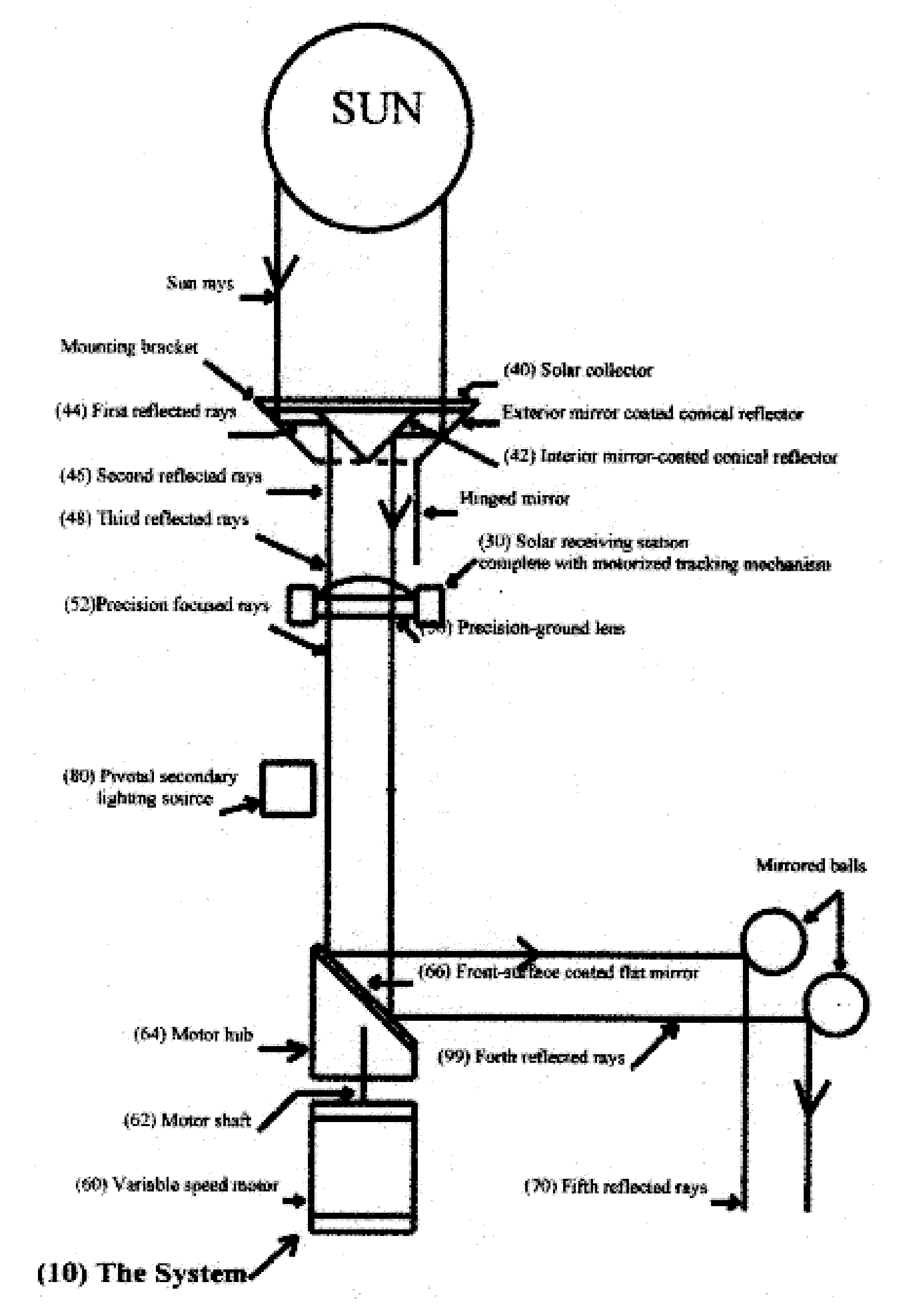
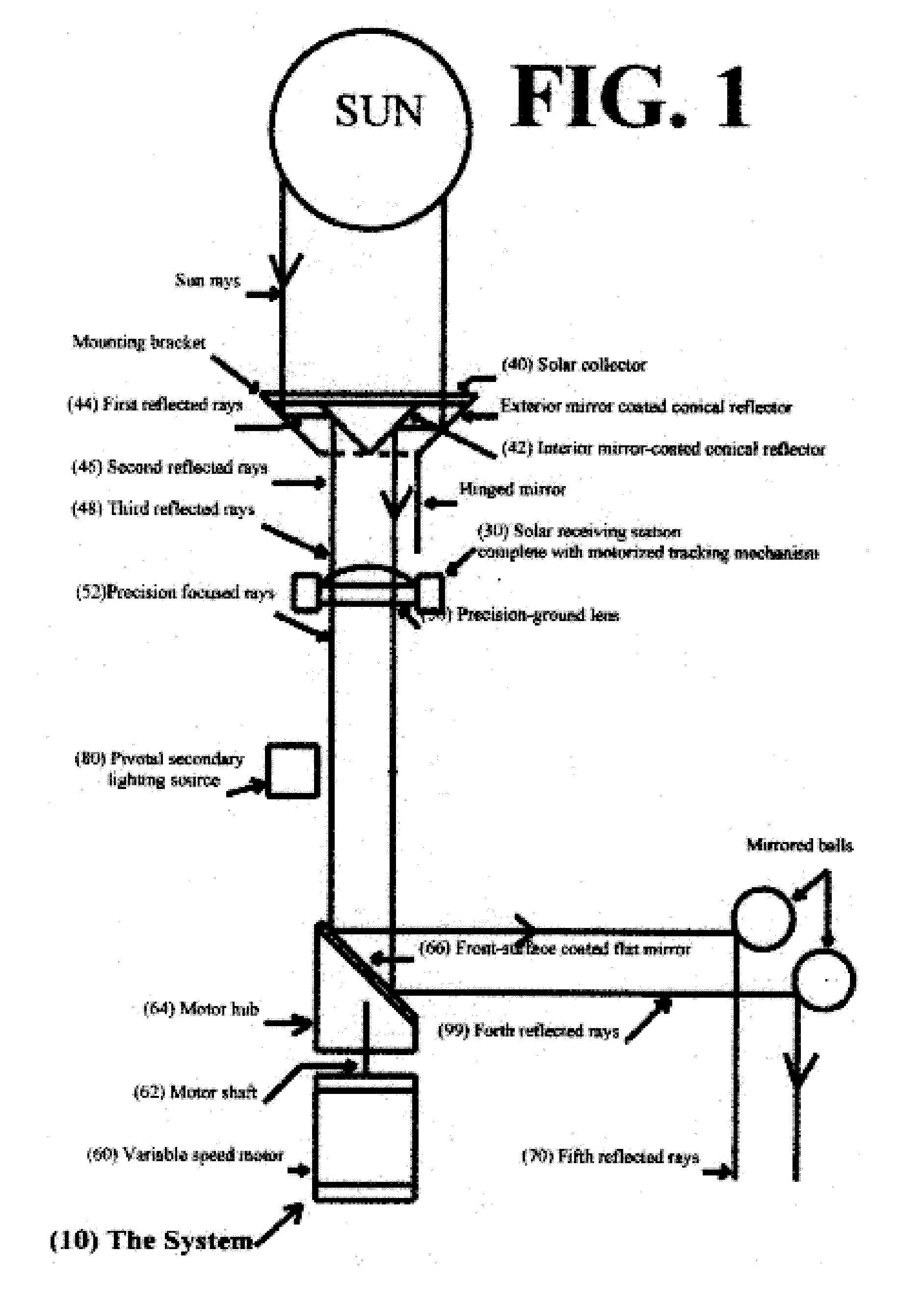
[0015]In reference to the FIG. 1 drawing, on page 7:

[0016]The Sun 20 emits solar rays 22 and they are reflected (first reflected rays) 44 from the solar collector (Exterior mirror coated conical reflector) 40 to the Interior mirror coated conical reflector 42 where the sun rays are again reflected (second reflected rays) 46 and down to the hinged mirror (third reflected rays), and on down to the precision-ground lens 50 (third reflected rays).

[0017]It should be pointed out that by increasing the diameter of the Exterior mirror coated conical reflector 40, of the solar collector, will transmit a more intense amount of light to the Interior mirror coated conical reflector 42. The precision-ground lens 50 converts the somewhat random solar rays into a coherent beam of light designated Precision focused rays 52, much like a laser beam, where it is reflected (forth reflected rays) 99 from the front-surface coated flat mirror 66 which is attached to the motor hub 64 and which, in turn, is...


PUM


Abstract

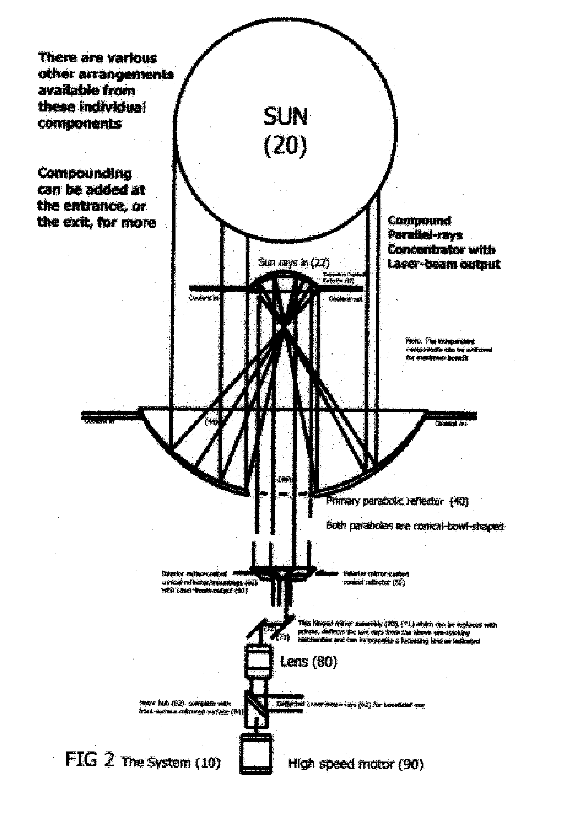
FIG. 1 (page 7), a rudimentary drawing showing a representation of a Rotating Sunlight / Light Beam for Fractional / Beneficial Use (alternative energy solar / light collection and distribution system), including second source backup.The Sun a giant laser, being 93 million miles from Earth, is the greatest point-source light in existence. The light-rays emanating from the Sun as photons, traveling 93 million miles in distance is a nearly-perfectly collimated form. The intent of this invention is to capture those highly collimated light-ray photons and gently redirect them in several directions, while greatly compounding them and keeping them in a highly parallel form to be delivered to the final destination.The second source light is composed of the invention on page 9, in which the Sun's location is replaced by the HID element in a newly invented form for capturing and compounding the light-rays. Compounding can he even greater as indicated on page 10.FIG. 3, page 9 is a drawing illustrating “one” preferred embodiment of a new type laser-like light bulb lamp, spotlight-searchlight. The sealed enclosures component can be cooled by heat exchangers and be fitted with serviceable connections to allow for the replenishment of the necessary elements to keep it in service indefinitely.The emitted light rays of the HID are reflected from various surfaces, re-directed to the convex or convexo-concave lens assembly. From there the light rays are redirected to the focal point of the second “parabolic” reflector where the light rays are once again reflected down / out through the lens, to be used for the intended purpose. The light rays that do not first arrive at the focal point of the parabolic reflector are re-circulated / redirected, perhaps to the rear flat-surface front-coated mirror and are redirected, by a circuitous routes back towards the focal point of the second “parabolic” reflector, and from there on through the lens assemblies for beneficial use.

Description

BACKGROUND OF THE INVENTION[0001]1. Field of Invention[0002]The present invention relates generally to light-energy distribution systems and more particularly to a solar-energy lighting system for reducing energy consumption and improving consumption efficiency.[0003]2. Description of the Prior Art[0004]Recently the cost of energy has increased sharply. Although recent increases are due in large part to artificial factors such as the maintenance of oil prices by large cartels, the increases also reflect the growing scarcity of energy producing fuels.[0005]In order to lessen the immediate impact of such scarcities as well as to postpone the inevitable day when these fuels are exhausted, it is in the public interest that everyone should conserve energy. Of course, the previous increases in the cost of energy coupled with the inevitable larger future increases make conservation even more individually attractive.[0006]Unfortunately, many energy consuming lighting devices and their loads...

Claims


Application Information

Patent Timeline
Patent Type & Authority Applications(United States)
IPC IPC(8): H01L31/00F24S23/30
CPCF24J2/06F24J2/08F24J2/18Y02B10/20G01S3/7861Y02E10/44Y02E10/47F24J2/54F24S23/00F24S23/30F24S23/79F24S30/40F24S50/20
Inventor WALDEN, SR., JACK O'NEAL
Owner WALDEN JACK ONEAL
Learn More