
System and method of carbon capture and sequestration

a carbon capture and sequestration system technology, applied in the field of carbon capture and sequestration systems and methods, can solve the problems of increasing transportation costs and difficulty, difficult to achieve in standard physical separation processes, and inability to permanently sequester cosub>2 /sub>, and achieves low cost and low energy consumption.

Active Publication Date: 2010-04-08
EXPANSION ENERGY
View PDF17 Cites 29 Cited by
  • Summary
  • Abstract
  • Description
  • Claims
  • Application Information

AI Technical Summary

Benefits of technology

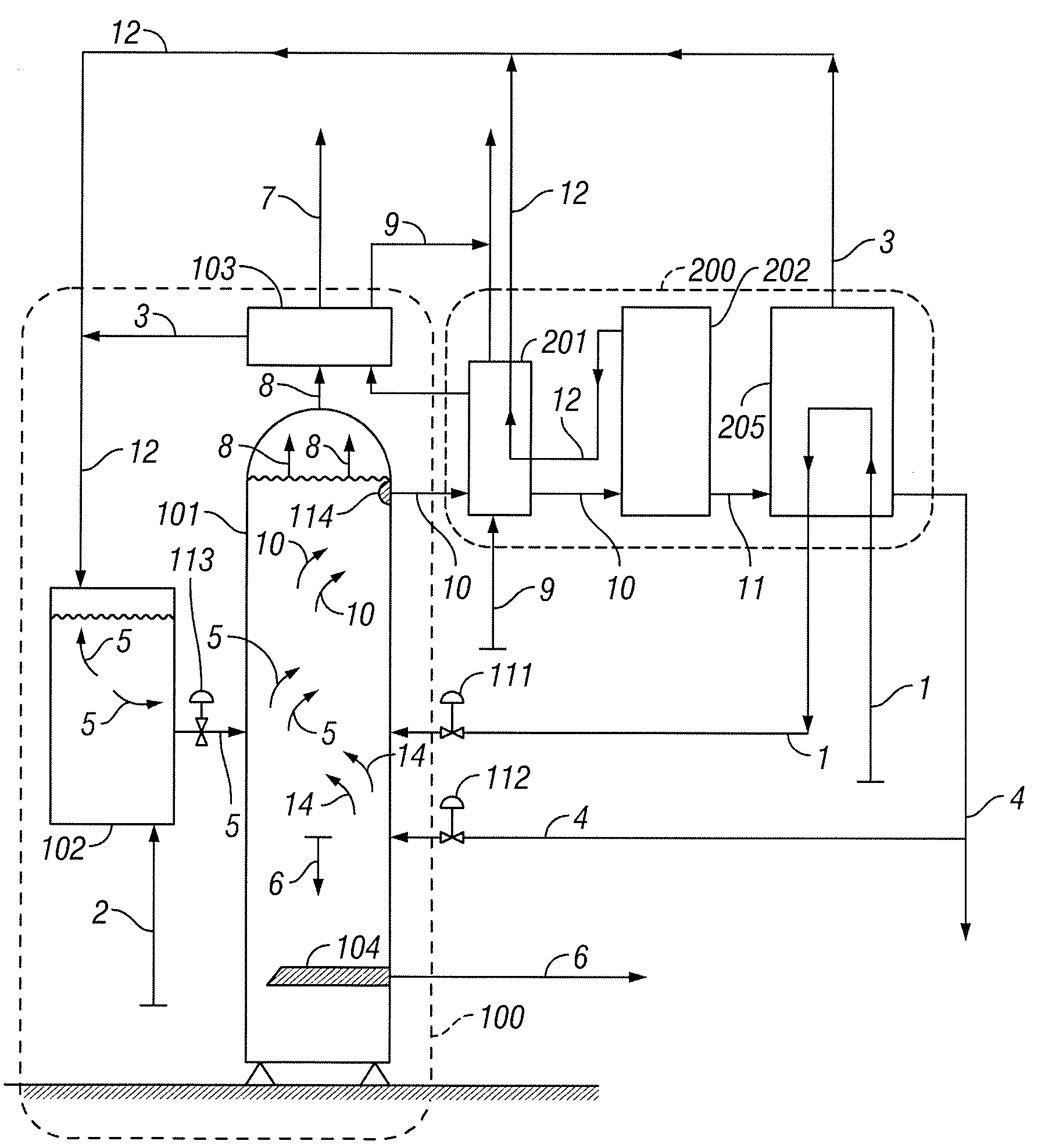
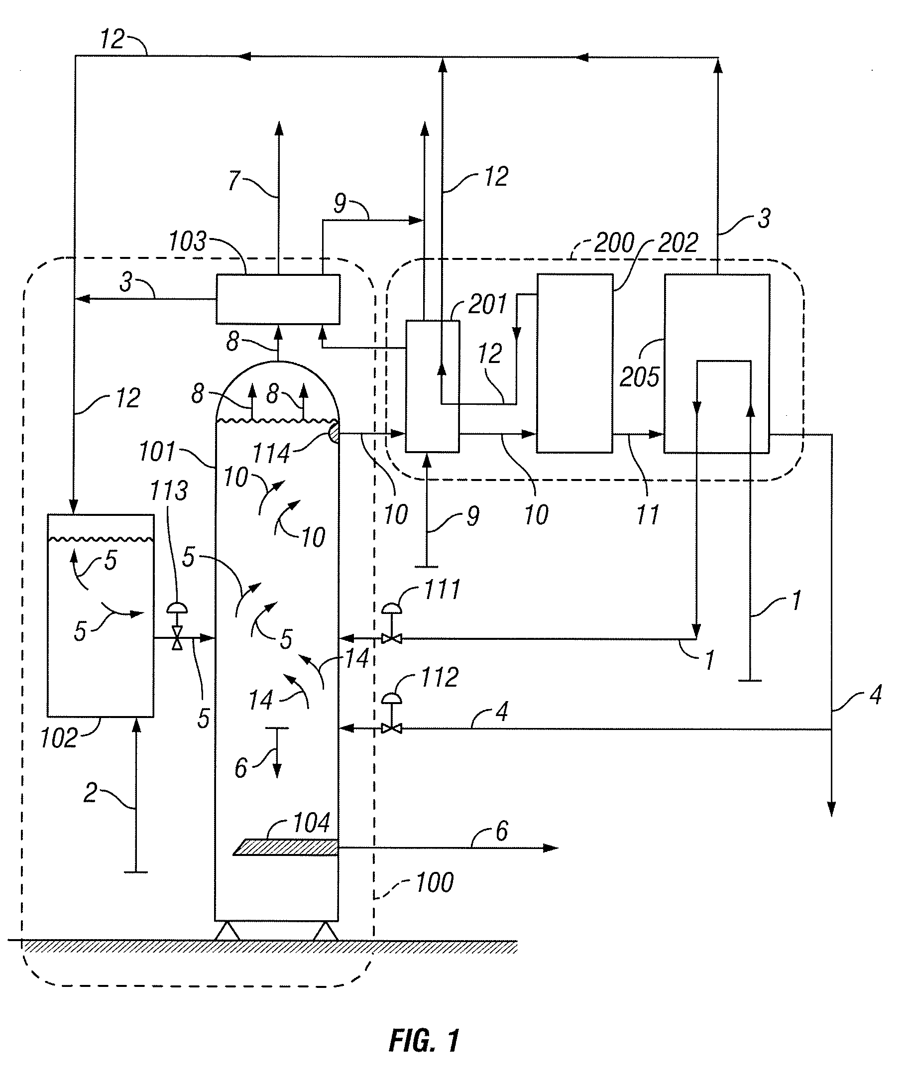
[0009]The present invention, in its many embodiments, alleviates to a great extent the disadvantages of known carbon capture and sequestration methods by providing a chemical process by which carbon dioxide in the form of carbonic acid is reacted with an alkali to form water and a dry, easily-removable carbonate that precipitates out of solution. Carbon dioxide sequestration is achieved by the above-ground disposal of the resulting carbonate. This process allows for industrial scale CO2 capture and sequestration at relatively low costs. Embodiments of the present invention also provide permanent, on-site CO2 capture and sequestration requiring relatively low energy consumption.
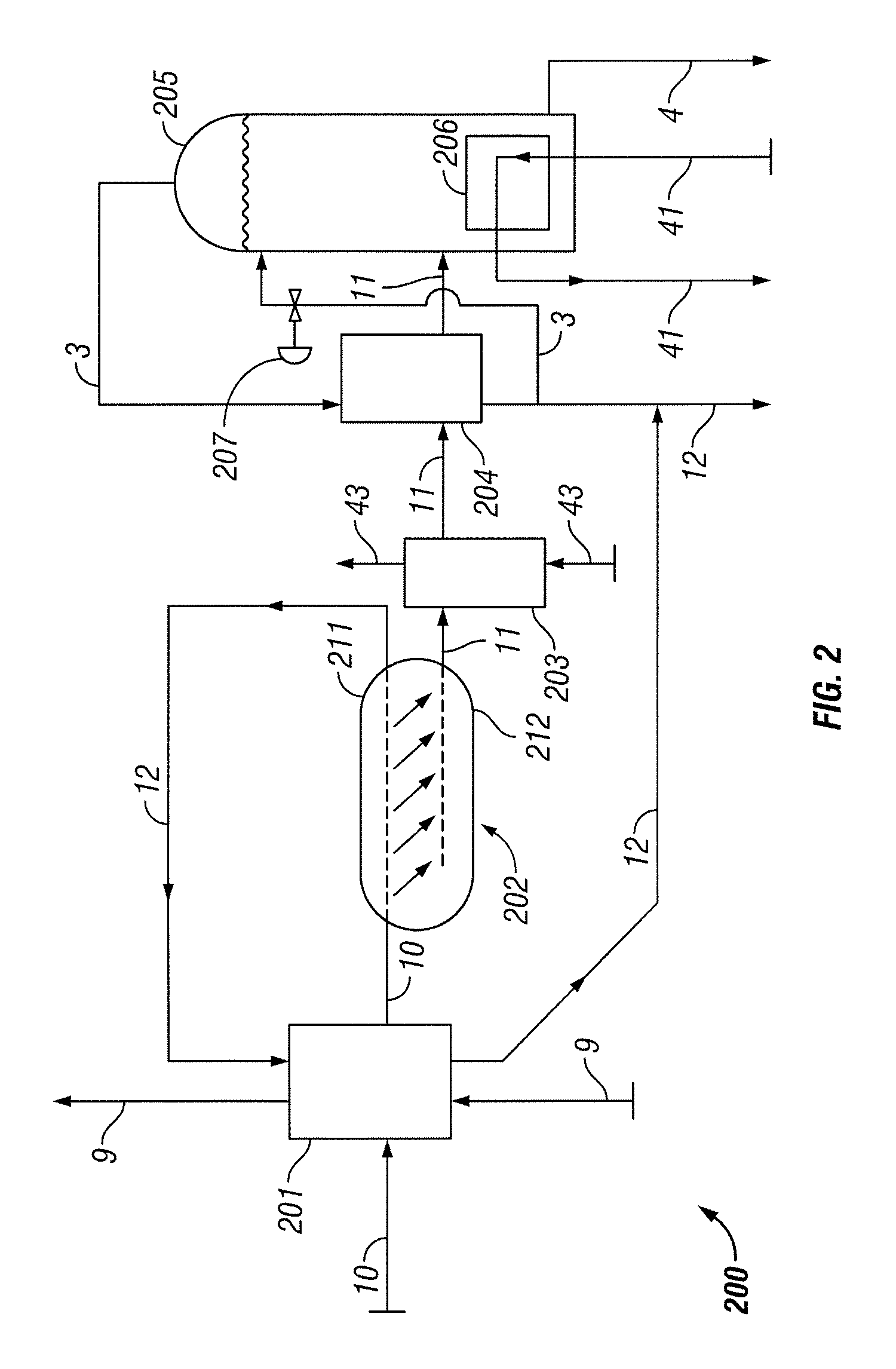
[0016]Embodiments of the present invention include methods of using nitrogen from the flue gas to provide cooling for the carbon capture and sequestration process. The method may include liquefying the nitrogen and recovering refrigeration from the liquefied nitrogen. The recovered refrigeration from the nitrogen is then used to cool the solvent and provide cooling for the solvent regeneration steps. This use of nitrogen for cooling increases the energy efficiency of embodiments of the invention.
[0018]A second portion of the nitrogen may be used to enhance the power output of a power plant. In a preferred embodiment, a first portion of this substantially liquefied nitrogen is compressed and heated. The heated compressed nitrogen is directed to a steam cycle of a power plant to enhance the power output of the power plant. A second portion of this substantially liquefied nitrogen may be stored in a storage apparatus. The second portion of the substantially liquefied nitrogen is pressurized by pumping it to pressure. It is then vaporized and directed through a hot gas expander to enhance the power output of the power plant. A third portion of this liquefied nitrogen is sold to off-site customers for a variety of uses, including as a refrigerant and as a fluid to enhance oil and gas well recovery. In a preferred embodiment the liquefied nitrogen is further refined by removing liquid argon, which is approximately 0.9% of the volume of the recovered nitrogen stream, and which is a high-value product that may also be sold in the marketplace.
[0024]Some embodiments may include a nitrogen liquefaction assembly which substantially liquefies nitrogen contained in the flue gas and recovers refrigeration from the substantially liquefied nitrogen. The recovered refrigeration from the nitrogen may be used to cool the solvent and to provide cooling for the solvent regeneration assembly. That portion of the liquid nitrogen is sent to the regeneration assembly under pressure, having been pumped to pressure by a cryogenic pump. The solvent regeneration assembly heats a first portion of the substantially liquefied nitrogen and directs the heated nitrogen to a steam cycle of a power plant to enhance the power output of the power plant. A storage apparatus stores a second portion of the substantially liquefied nitrogen, releases the second portion of the substantially liquefied nitrogen, and directs it to a hot gas expander to enhance the power output of a power plant.

Problems solved by technology

However, the capture media need to be regenerated without releasing the CO2 into the atmosphere, and this is difficult to achieve in standard physical separation processes.
However, very specific geological configurations are required for disposal of the CO2, and these are not commonly available at CO2 emission sites.
Thus, transportation adds substantial cost and difficulty.
In addition, it is not known whether CO2 can be permanently sequestered underground.
The two-step approach also is not economical because often CO2 represents only a small percentage of a large volume of flue gas, and treating a large flow stream to recover a small portion of it as CO2 is wasteful and expensive.
But this requires a good deal of heat and pressure.
The energy input and environmental costs of mining the rock and transporting it to and from the CO2 source, as well as the energy costs of having the crushed rock accept and absorb the CO2, are very high.
All of these methods have the problem that the absorption media need to be regenerated without losing CO2.
However, a significant drawback of that approach is that the carbonate exits the process in solution with water, requiring further, energy intensive treatment to separate the solids and the water, or it results in a large volume, heavy, wet, cement-like paste that requires energy intensive drying and mechanical systems to control the size, configuration and weight of the resulting dried product.
Although some are examining techniques for capturing and sequestering CO2 from ambient air, they are not suitable for CO2 emissions from power plants because of the substantial difference in CO2 concentration between ambient air and flue gas.
Removing very small quantities of CO2 from the very large quantities of ambient air is not as viable and as productive as the capture and sequestration of large amounts of CO2 from streams, such as flue gas, where the CO2 is more concentrated.
Specifically, there is a need for a carbon capture system that does not use capture media that require complex and energy-intensive regeneration, and does not yield a heavy, wet end product that requires energy intensive drying and other post-capture processing.

Method used


Image

  • System and method of carbon capture and sequestration
  • System and method of carbon capture and sequestration
  • System and method of carbon capture and sequestration

Examples


Embodiment Construction

[0033]In the following paragraphs, embodiments of the present invention will be described in detail by way of example with reference to the accompanying drawings, which are not drawn to scale, and the illustrated components are not necessarily drawn proportionately to one another. Throughout this description, the embodiments and examples shown should be considered as exemplars, rather than as limitations on the present invention. As used herein, the “present invention” refers to any one of the embodiments of the invention described herein, and any equivalents. Furthermore, reference to various aspects of the invention throughout this document does not mean that all claimed embodiments or methods must include the referenced aspects. Reference to temperature, pressure, density and other parameters should be considered as representative and illustrative of the capabilities of embodiments of the invention, and embodiments can operate with a wide variety of such parameters. It should be ...


PUM

PropertyMeasurementUnit
heightaaaaaaaaaa
temperaturesaaaaaaaaaa
heataaaaaaaaaa

Abstract

Systems and methods of capturing and sequestering carbon dioxide, comprising mixing a substantially non-aqueous solvent and an alkali such that the solvent and alkali form a solvent suspension, mixing water and a flue gas containing carbon dioxide with the solvent suspension such that a reaction occurs, the reaction resulting in the formation of a carbonate, water and heat.

Description

FIELD OF THE INVENTION[0001]The present invention relates to carbon capture and sequestration systems and methods.BACKGROUND[0002]The capture and sequestration of carbon dioxide (CO2) emissions needs to be significantly improved if the climate change consequences of such emissions are to be controlled or curtailed. The CO2 produced from combustion and industrial processes, specifically power plant flue gas, is perhaps the largest single greenhouse gas emission. Most existing carbon capture and sequestration methods take a two-step approach. First, a method is sought for separating CO2 from the flue gas or other gaseous emission source. These may include capture of the CO2 in liquid solvents, solid zeolyte or various membranes. However, the capture media need to be regenerated without releasing the CO2 into the atmosphere, and this is difficult to achieve in standard physical separation processes.[0003]The second step is sequestering the CO2 gas or liquid by inserting it into undergr...

Claims


Application Information

Patent Timeline
Patent Type & Authority Applications(United States)
IPC IPC(8): B01D3/40C01B32/60
CPCF25J2230/30F25J1/0204F25J2270/16B01D53/62Y02C10/06F25J1/004B01D53/1493F25J1/007F25J1/0015Y02C10/04F25J1/0072F25J1/0288F25J2220/44F25J2220/02B01D53/1475F25J1/005B01D2257/404F25J1/0284B01D2257/504F25J2230/20Y10S210/908B01D2251/30B01D2258/0283F25J2210/70Y02C20/40
Inventor VANDOR, DAVID
Owner EXPANSION ENERGY
Learn More