Method and Apparatus for Producing Samples for Transmission Electron Microscopy

a transmission electron microscope and sample technology, applied in the direction of engine lubrication, liquid/fluent solid measurement, laser, etc., can solve the problems of reducing to below 1 nm, a multiplicity of partially very complex technologies for producing adequately thin, and a lack of electron-transparent areas on tem samples, etc., to achieve the effect of small damage, fast production, and effective localization and reproduction

Inactive Publication Date: 2010-04-15
3D MICROMAC AG
View PDF30 Cites 19 Cited by
  • Summary
  • Abstract
  • Description
  • Claims
  • Application Information

AI Technical Summary

Benefits of technology

[0015]It is one object of the invention to provide a method for producing samples for transmission electron microscopy which enables TEM samples to be produced quickly in a way that can be localized effectively and reproduced and causes little damage in conjunction with a multiplicity of different sample materials.
[0016]It is another object of the invention to enable cross-sectional preparations made from materials provided with layer structures, for example structured semiconductor materials, to be obtained in an accurate and reproducible fashion with little damage.

Problems solved by technology

Up to a few years ago, the electron optical systems used in transmission electron microscopes were not sufficiently good to allow images and analyses at the theoretical spatial resolution limit.
Moreover, there is presently a multiplicity of partially very complex technologies for producing adequately thin, electron-transparent areas on TEM samples.
According to results of relevant investigations, a reduction to below 1 nm is scarcely possible even when use is made of low-energy ion beams (typically 200 eV to 500 eV energy).
However, the possibilities for using the method are restricted, because it can be used in essence only with sample materials with crystallographically defined cleavage planes.
Furthermore, it is difficult to impossible for it to be automated.
Finally, it is scarcely possible to implement even a target preparation, since the exact location of the crack initiation cannot be determined accurately enough owing to the coarse scoring.
It is particularly difficult and complicated to prepare cross-sectional preparations that are intended to enable examination of layers, layer systems or structured surfaces substantially perpendicular to the surface normals of the layer structures.
It is becoming increasingly evident that the preparation of high-quality TEM samples with sufficiently thin electron-transparent areas is the step which is limiting throughput.
This circumstance is frequently countered by procuring a number of preparation machines, but this, by way of example, is associated with high costs in the case of systems for focused ion beam (FIB) processing.

Method used


Image

  • Method and Apparatus for Producing Samples for Transmission Electron Microscopy
  • Method and Apparatus for Producing Samples for Transmission Electron Microscopy
  • Method and Apparatus for Producing Samples for Transmission Electron Microscopy

Examples


Embodiment Construction

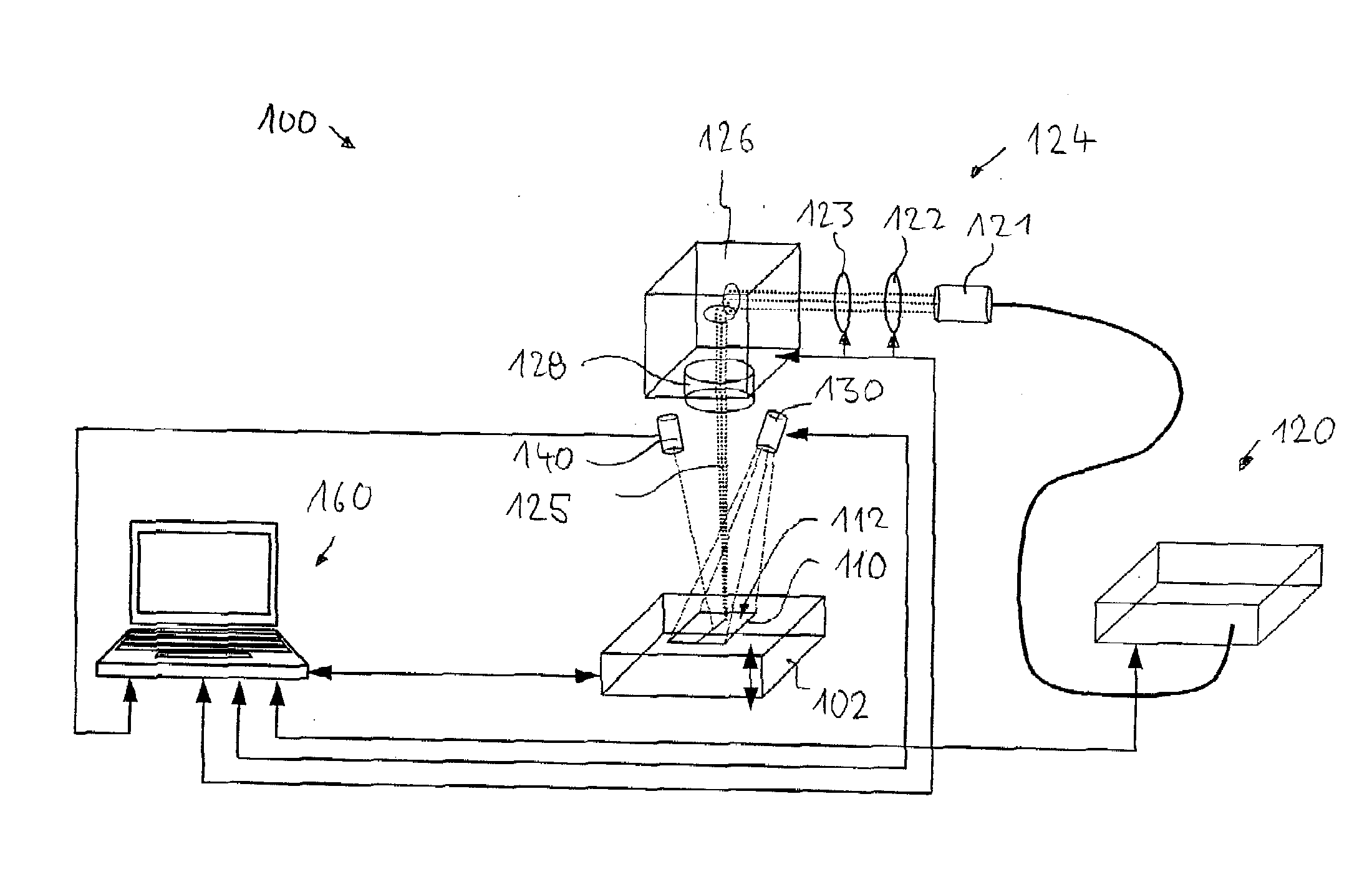
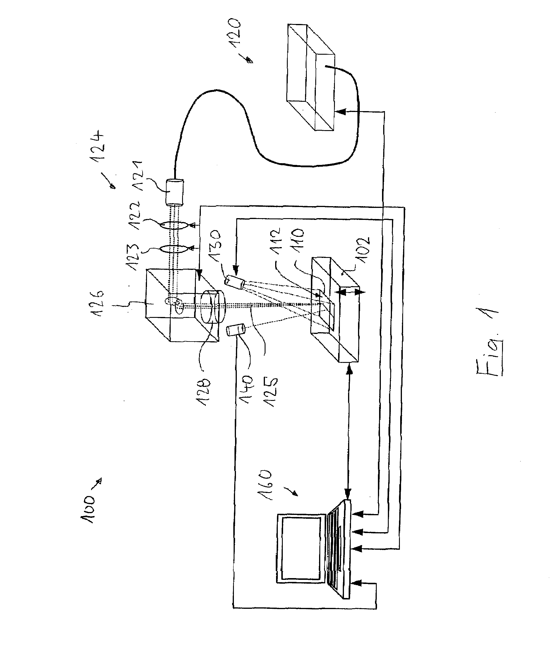
[0060]FIG. 1 shows a diagrammatic illustration of essential components of an apparatus 100 for producing samples for transmission electron microscopy with the aid of focused laser radiation. The apparatus, which is also referred to as a sample preparation apparatus 100 below, is a laser microprocessing station which is designed as a table appliance and whose components are specifically designed for the purpose and coordinated with one another in order semiautomatically or fully automatically to produce from preprocessed or not specifically preprocessed substrates of different sample materials TEM samples which are suitable for ultrahigh resolution TEM examinations, in particular for TEM examinations with the aid of modern, aberration-corrected transmission electron microscopes largely with the avoidance of preparation artefacts (for example, near-surface amorphization).

[0061]A lifting table 102 which can be driven by an electric motor and functions as substrate holder for holding at...


PUM

PropertyMeasurementUnit
acute angleaaaaaaaaaa
thicknessaaaaaaaaaa
thicknessaaaaaaaaaa

Abstract

In the case of a method for producing samples for transmission electron microscopy, a sample is prepared from a substrate of a sample material. To this end, the sample material is irradiated by means of a laser beam along an irradiation trajectory in order to produce a weak path in the sample material. The irradiation is controlled such that the weak path crosses a further weak path, which is likewise preferably produced by laser irradiation, running in the sample material, at an acute angle in a crossing region. The substrate is broken along the weak paths. A sample is thereby produced which has a wedge-shaped sample section bounded by fracture surfaces and has in the region of a wedge tip at least one electron-transparent region.

Description

[0001]The following disclosure is based on German Patent Application No. 10 2008 052 006.3 filed on Oct. 10, 2008, which is incorporated into this application by reference.BACKGROUND OF THE INVENTION[0002]1. Field of the Invention[0003]The invention relates to a method for producing samples for transmission electron microscopy, and to an apparatus suitable for carrying out the method.[0004]2. Description of the Related Prior Art[0005]Since their introduction in the 1930s, transmission electron microscopes have found wide application in various branches of science and industry. Because of the resolution which is substantially better by comparison with light microscopy and lies in the sub-angstrom range for the currently best appliances, the microstructure and nanostructure of various types of preparations can be examined in great detail.[0006]Particularly in the field of characterization of solids, information can be obtained on the atomic scale with the aid of transmission electron ...

Claims


Application Information

Patent Timeline
Patent Type & Authority Applications(United States)
IPC IPC(8): G01N23/00G21K5/00
CPCG01N1/286H01J2237/31745G01N2001/2886
Inventor HOECHE, THOMAS
Owner 3D MICROMAC AG
Why Eureka
Try Eureka