
Grid for vacuum electron device and method for manufacture of same

a vacuum electron and grid technology, applied in the manufacture of discharge tube main electrodes, electrode systems, electric discharge tube/lamps, etc., can solve the problems of inability of carbon atoms to diffuse and realign in any meaningful timescale, discontinuities often act as crack initiation sites, and products are particularly fragile and subject to warping, so as to reduce the probability of handling damage, simplify the assembly of the grid, and increase the concentricity

Inactive Publication Date: 2010-04-15
COMM & POWER IND
View PDF6 Cites 9 Cited by
  • Summary
  • Abstract
  • Description
  • Claims
  • Application Information

AI Technical Summary

Benefits of technology

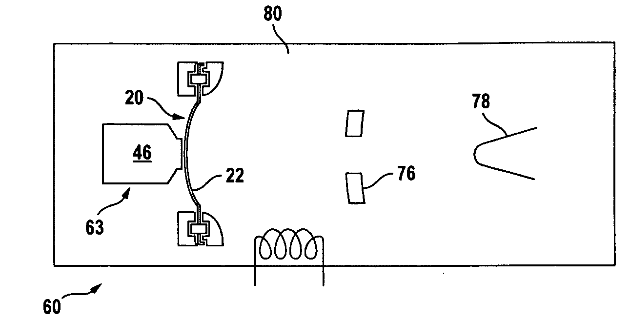
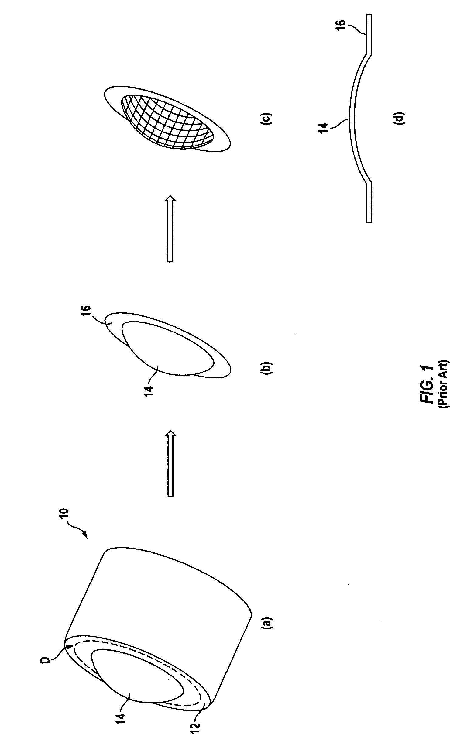
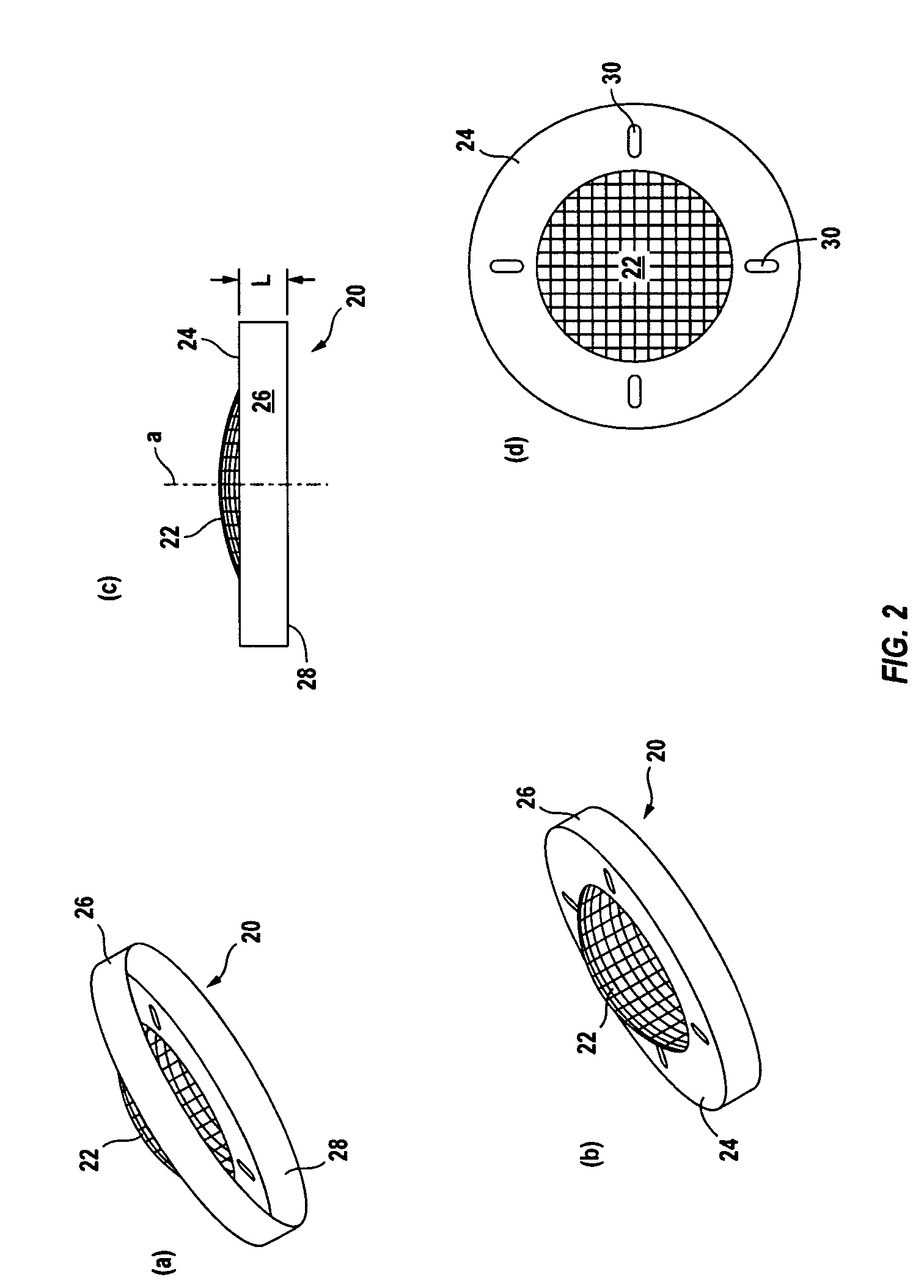
[0027]Since, during fabrication of the mandrel 50, the mandrel exterior and the skirt template 70 are machined in the same CNC operation, there is an inherent increase in concentricity between the dome portion 66, the flange portion 68 and the skirt portion 72 of the blank 54, and of the corresponding dome 22, flange 24 and skirt 26 of the resultant grid component 20. This increased concentricity simplifies assembly of the grid to the electron gun (not shown) of the VED device, by eliminating multiple steps in the precision alignment sequence. Moreover, the skirt 26 itself adds considerable stiffness, thereby lessening the probability of handling damage. An advantageous feature of the precursor skirt portion 72 is that it adds considerable resistance to deformation and warping of the cup dome portion 66 and flange portion 68 during processing. Residual thermal stresses are characteristic of all pyrolytic graphite depositions, and in this thickness regime, the grid blank 54 is subject to significant warping. Although the grid blank is fabricated out of pyrolytic graphite, concerns for thin-wall metal machining and forming parts are paralleled in the net effect.

Problems solved by technology

This contiguity restriction results from the inability of the carbon atoms to diffuse and realign in any meaningful timescale at the deposition temperature (nominally about 1700-2200° C.) and below.
As a result, discontinuities often act as crack initiation sites.
Even when the residual thermal stresses are not immediately manifested, they render the product particularly fragile and subject to warping, or “potato-chipping,” at handling, assembly, and during normal operation.

Method used


Image

  • Grid for vacuum electron device and method for manufacture of same
  • Grid for vacuum electron device and method for manufacture of same
  • Grid for vacuum electron device and method for manufacture of same

Examples


Embodiment Construction

[0019]The description herein is provided in the context of a grid for a vacuum electron device (VED) and a method for manufacturing of same. Those of ordinary skill in the art will realize that the following detailed description is illustrative only and is not intended to be in any way limiting. Other embodiments will readily suggest themselves to such skilled persons having the benefit of this disclosure. Reference will now be made in detail to implementations as illustrated in the accompanying drawings. The same reference indicators will be used throughout the drawings and the following detailed description to refer to the same or like parts.

[0020]In the interest of clarity, not all of the routine features of the implementations described herein are shown and described. It will, of course, be appreciated that in the development of any such actual implementation, numerous implementation-specific decisions must be made in order to achieve the developer's specific goals, such as comp...


PUM


Abstract

A grid component for use with a vacuum electron device (VED), such as an inductive output tube (IOT), includes a skirt that adds structural support and aids in alignment. The grid component has a dome in which a grid pattern is formed and includes an annular, concentric flange surrounding the dome. The skirt is formed concentrically around the flange. Alignment orifices may be provided in the flange for passage of alignment pins in the assembled product. The grid, flange, and skirt are a unitary component and are formed by a chemical vapor deposition (CVD) or similar process, in which a mandrel is used to provide a deposition surface. The mandrel is placed in a furnace, and a high-temperature CVD process is used to break down a hydrocarbon gas to thereby deposit a pyrolytic graphite coating onto the mandrel. The mandrel may include a skirt template to provide the characteristic skirt.

Description

CROSS-REFERENCE TO RELATED APPLICATIONS[0001](Not applicable)BACKGROUND[0002]1. Field of the Invention[0003]The present invention relates to grids for linear beam RF (radio frequency) vacuum tube devices having an electron emitting cathode and an RF-modulated grid closely spaced thereform.[0004]2. Description of the Related Art[0005]It is well known in the art to utilize a vacuum electron (VED) device, such as a klystron or traveling wave tube amplifier, to generate or amplify high frequency RF energy. Such devices generally include an electron-emitting cathode and an anode spaced therefrom. In the case of IOTs (Inductive Output Tubes) and similar devices, a grid is also included, positioned in an inter-electrode region between the cathode and the anode. Grid-to-cathode spacing is critical and is directly related to the performance and longevity of the linear beam device. The material of the grid is typically pyrolytic graphite (PG), selected for its excellent thermal properties.[00...

Claims


Application Information

Patent Timeline
Patent Type & Authority Applications(United States)
IPC IPC(8): H01J25/00H01J9/00
CPCH01J1/46H01J25/04H01J23/065H01J9/14
Inventor EISEN, EDWARD LAWRENCEKLINE, JAMES ERIC
Owner COMM & POWER IND
Learn More