Light Emissive Device

a light emissive device and light emissive technology, applied in the direction of discharge tube luminescnet screen, discharge tube/lamp details, luminescent composition, etc., can solve the problem that the application is not aware of the successful fabrication of such oleds for practical use, and achieves the reduction or elimination of quenching problems, good colour stability, and high triplet energy

Inactive Publication Date: 2010-04-22
CDT OXFORD +1
View PDF41 Cites 10 Cited by
  • Summary
  • Abstract
  • Description
  • Claims
  • Application Information

AI Technical Summary

Benefits of technology

[0025]According to an embodiment of the present invention, the composition comprises a further organic light emissive material which has a different colour emission. The further organic light emissive material may be a fluorescent material such as, for example, a blue fluorescent material. It has been found that the combination of a blue fluorescent material with fluorescent and phosphorescent red materials is useful in forming a white emissive device having good colour stability. However, it is envisaged that other combinations of materials utilizing the present inventive concept may be provided. For example, it is possible to produce a colour stable device comprising fluorescent and phosphorescent materials having a first colour, fluorescent and phosphorescent materials having a second colour different to the first colour, and a further light emissive material. Such a device may be a white emissive device comprising fluorescent and phosphorescent red materials, fluorescent and phosphorescent green materials, and a fluorescent blue material. Here, the colour stability of both the red and green materials is accounted for.
[0026]One might expect that the emission from the phosphorescent material would be quenched by the fluorescent material of the same colour. However, it has surprisingly been found that this is not the case. Preferably, the phosphorescent and fluorescent material of the same colour are provided in low concentrations in the composition, for example, less than 5 mol % relative to the further light emissive material, more preferably less than 1 mol %. It has been postulated that by providing a red or yellow phosphorescent and red or yellow fluorescent material colour at low concentration relative to a blue light emissive material, problems with quenching are reduced or eliminated because the predominant component of the composition is the blue light emissive material which has a higher triplet energy than the red phosphorescent material.

Problems solved by technology

However, whilst proposals have been made to fabricate OLEDs capable of producing light with CIE (Commission Internationale d'Eclairage) coordinates approximating to white, the present applicants are not aware of such OLEDs being successfully fabricated for practical use.

Method used


Image

  • Light Emissive Device
  • Light Emissive Device
  • Light Emissive Device

Examples


examples

[0075]A white emitting polymer comprising fluorescent blue emitting triarylamine repeat units of formula 4 and fluorescent red emitting repeat units of formula 8 was prepared by Suzuki polymerisation as described in WO 00 / 53656.

[0076]A red phosphorescent dendrimer material comprising tris-(phenylisoquinoline)iridium (III) was prepared as described in WO 02 / 066552.

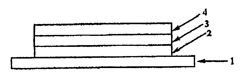
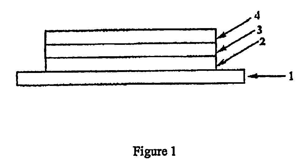
[0077]Poly(ethylene dioxythiophene) / poly(styrene sulfonate) (PEDT / PSS), available from H C Starck of Leverkusen, Germany as Baytron P® was deposited over an indium tin oxide anode supported on a glass substrate (available from Applied Films, Colo., USA) by spin coating. A hole transporting layer was deposited over the PEDT / PSS layer by spin coating from xylene solution to a thickness of about 10 nm and heated at 180° C. for 1 hour. A blend of the aforementioned fluorescent polymer and phosphorescent dendrimer was deposited over the layer of F8-TFB by spin-coating from xylene solution to a thickness of around 65 nm. A Ba / Al ...


PUM

PropertyMeasurementUnit
wavelengthaaaaaaaaaa

Abstract

A composition for use in an organic light emissive device, the composition comprising a fluorescent organic light emissive material and a phosphorescent organic light emissive material of the same colour.

Description

FIELD OF INVENTION [0001]The present invention relates to organic light emissive devices and to compositions for use in manufacturing organic light emissive devices.BACKGROUND OF THE INVENTION[0002]Organic light emissive devices (OLEDs) generally comprise a cathode, an anode and an organic light emissive region between the cathode and the anode. Light emissive organic materials may comprise small molecular materials such as described in U.S. Pat. No. 4,539,507 or polymeric materials such as those described in PCT / WO90 / 13148. The cathode injects electrons into the light emissive region and the anode injects holes. The electrons and holes combine to generate photons.[0003]FIG. 1 shows a typical cross-sectional structure of an OLED. The OLED is typically fabricated on a glass or plastic substrate 1 coated with a transparent anode 2 such as an indium-tin-oxide (ITO) layer. The ITO coated substrate is covered with at least a layer of an electroluminescent organic material 3 and cathode m...

Claims


Application Information

Patent Timeline
Patent Type & Authority Applications(United States)
IPC IPC(8): C09K11/06H01J1/63
CPCC08G61/123H05B33/14C08G61/125C08G61/126C08G73/0266C08L65/00C09K11/06C09K2211/1007C09K2211/1029C09K2211/1433C09K2211/1458C09K2211/1483C09K2211/1491C09K2211/185H01L51/0036H01L51/0037H01L51/0043H01L51/0085H01L51/5012C08G61/124H10K85/113H10K85/1135H10K85/151H10K85/342H10K50/11C08G73/02C08L79/02H10K85/00C09K2211/1466C09K2211/18H10K85/111H10K50/00
Inventor WILSON, RICHARD
Owner CDT OXFORD
Why Eureka
Try Eureka