

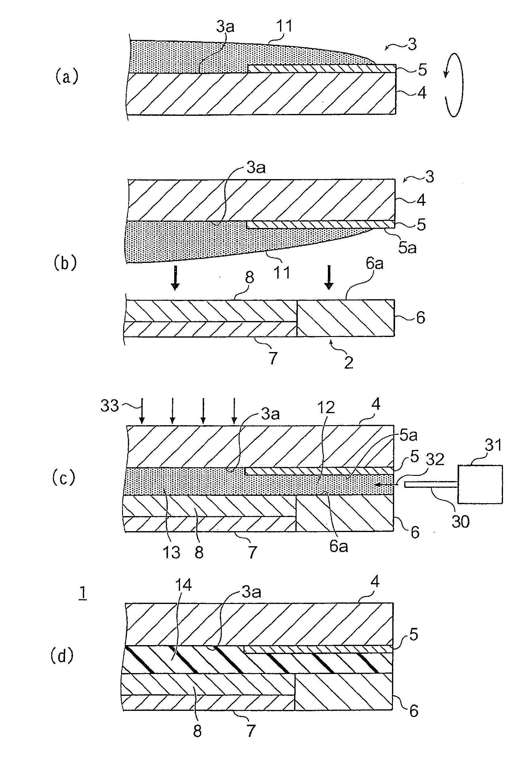
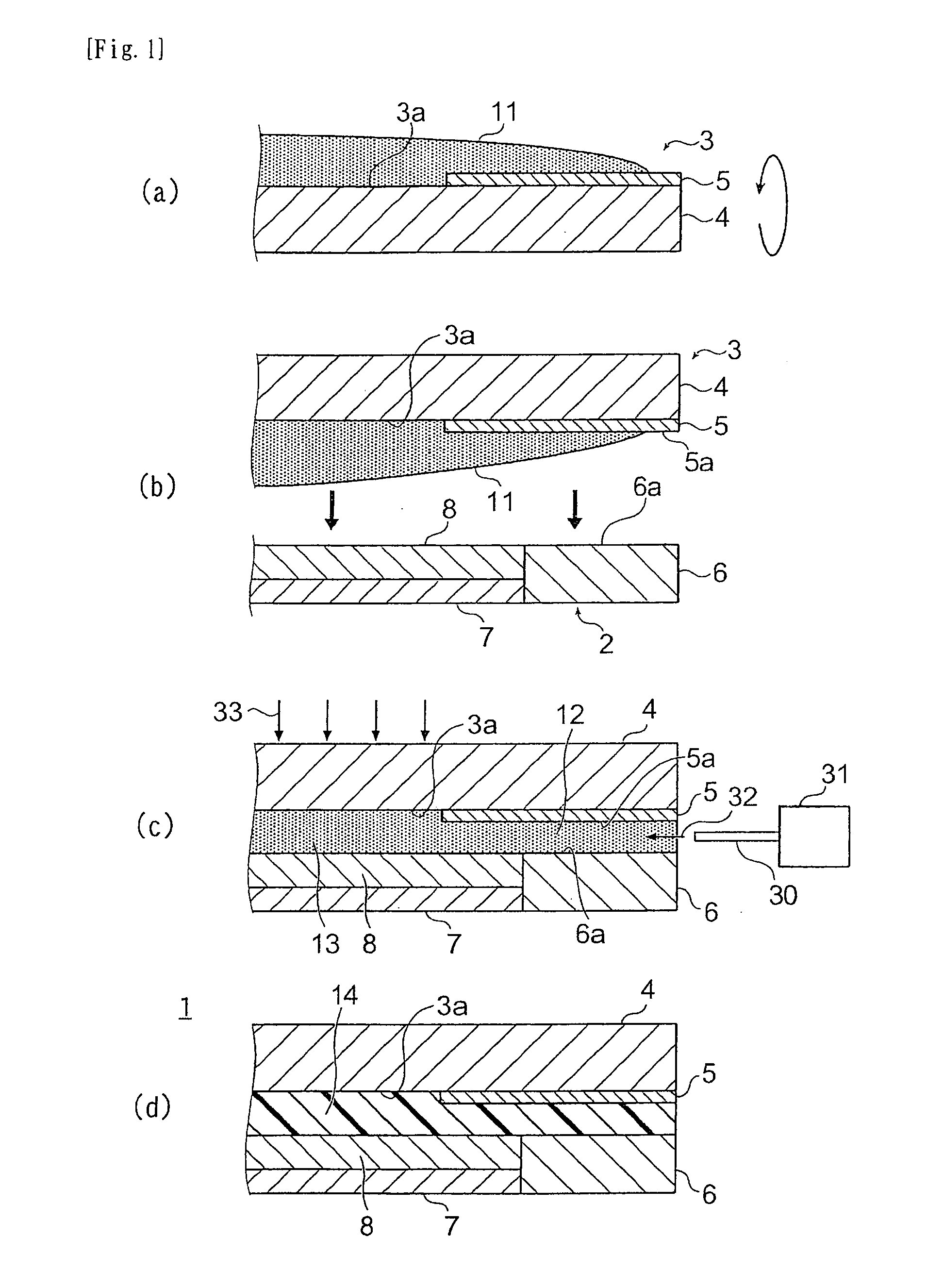
Method for producing image display apparatus
a technology of image display and display panel, which is applied in the direction of instruments, coatings, optics, etc., can solve the problems of image defects, difficult to produce thinner display panels, and reduced contrast and luminance, and achieve high contrast, high luminance, and high-quality image display
- Summary
- Abstract
- Description
- Claims
- Application Information
AI Technical Summary
Benefits of technology
Problems solved by technology
Method used
Image

Examples
examples
[0110]The present invention will now be described in more detail using the following examples and comparative examples. However, the present invention is not limited to these examples and comparative examples.
Coating Solution Preparation
example resin 1
[0111]The resin composition of Example 1 was prepared by kneading in a kneader 50 parts by weight of polyurethane acrylate (trade name: UV-3000B, manufactured by Nippon Synthetic Chemical Industry Co., Ltd.), 30 parts by weight of isobornyl acrylate (trade name: IBXA, manufactured by Osaka Organic Chemical Industry Ltd.), 3 parts by weight of a photopolymerization initiator (trade name: Irgacure 184, manufactured by Ciba Specialty Chemicals Inc.), and 1 part by weight of a photopolymerization initiator (trade name: SpeedCure TPO, manufactured by Nihon SiberHegner KK).
example resin 2
[0112]The resin composition of Example 2 was prepared by kneading in a kneader 70 parts by weight of an ester formed from a maleic anhydride adduct of a polyisoprene polymer and 2-hydroxyethyl methacrylate, 30 parts by weight of dicyclopentenyloxyethyl methacrylate, 10 parts by weight of 2-hydroxybutyl methacrylate, 30 parts by weight of a hydrogenated terpene resin, 140 parts by weight of a butadiene polymer, 4 parts by weight of a photopolymerization initiator, and 0.5 parts by weight of a visible region photopolymerization initiator.
PUM
| Property | Measurement | Unit |
|---|---|---|
| light transmittance | aaaaa | aaaaa |
| storage modulus | aaaaa | aaaaa |
| curing shrinkage ratio | aaaaa | aaaaa |
Abstract
Description
Claims
Application Information