Electrochemical energy source and electronic device

a technology of electronic devices and energy sources, applied in the direction of electrochemical generators, deferred-action cells, cell components, etc., can solve the problems of relatively poor battery performance and limited size of electrodes, and achieve the effects of improving the rate capacity of energy sources, increasing the surface area per footprint of electrodes, and increasing the contact surfa

Inactive Publication Date: 2010-04-22
KONINKLIJKE PHILIPS ELECTRONICS NV
View PDF0 Cites 13 Cited by
  • Summary
  • Abstract
  • Description
  • Claims
  • Application Information

AI Technical Summary

Benefits of technology

[0004]This object can be achieved by providing the electrochemical energy source according to the preamble, comprising: a substrate, and at least one cell deposited onto said substrate, the cell comprising: a first electrode, and a second electrode, said first electrode and said second electrode being separated by an electrolyte chamber for receiving an externally supplied electrolyte, wherein at least one electrode is provided with at least one patterned surface. By patterning or structuring one, and preferably both, electrodes of the reserve-type electrochemical energy source according to the invention, a three-dimensional surface area, and hence an increased surface area per footprint of the electrode(s), and an increased contact surface per volume between the at least one electrode and the externally supplied electrolyte is obtained. This increase of the contact surface(s) leads to an improved rate capacity of the energy source, and hence to a increased performance of the energy source according to the invention. In this way the power density in the energy source may be maximized and thus optimized. Due to this increased cell performance a small-scale energy source according to the invention will be adapted for powering a small-scale electronic device in a satisfying manner. Moreover, due to this increased performance, the freedom of choice of (small-scale) electronic components to be powered by the electrochemical energy source according to the invention will be increased substantially. The nature, shape, and dimensioning of the pattern may be various, as will be elucidated below. The externally supplied electrolyte may also be of various nature, wherein for example a substantially liquid-state electrolyte, such as (sea) water, blood, urine, saliva, may be used to activate the energy source according to the invention. However, it is also conceivable to provide the electrolyte chamber with a substantially solid-state electrolyte, a polymer-based electrolyte and / or a gel (gelatinous) electrolyte. The cell of the electrochemical energy source according to the invention is preferably a battery cell. However, in another preferred embodiment, the cell of the electrochemical energy source is a (bio)fuel cell. By implanting a bio fuel cell into a living human or animal body, the bio fuel cell will withdraw readily available bio fuels, such as e.g. glucose from the blood stream, from renewable sources and will convert them into benign by-products with the generation of electricity. Since a bio fuel cell uses concentrated renewable sources of chemical energy, a bio fuel cell commonly has a relatively high energy density and a relatively long lifetime, as a result of which a bio fuel cell can be made relatively small and light, and are hence ideally suitable to be implanted in a living human or animal body. In a particular preferred embodiment, the electrochemical energy source may comprise both a battery cell and a fuel cell, and may hence be considered as a hybrid energy source, in which chemical energy is converted into electrical energy with use of the bio fuel cell, which electrical energy may subsequently be stored in the battery cell to further improve the power output of the energy source according to the invention.
[0010]The electrochemical energy source preferably comprises at least one barrier layer being deposited between the substrate and at least one electrode, which barrier layer is adapted to at least substantially preclude diffusion of active species of the cell into said substrate. In this manner the substrate and the electrochemical cell will be separated chemically, as a result of which the performance of the electrochemical cell can be maintained relatively long-lastingly.
[0011]In a preferred embodiment, both the first electrode and the second electrode are deposited directly onto the substrate. Direct depositing of the electrodes onto the substrate facilitates manufacturing of the electrochemical energy source according to the invention. The space between both electrodes defines the electrolyte chamber. Stacking both electrodes on top of each other, wherein an open space is left between both electrodes, is relatively laborious to generate, and hence less preferable.

Problems solved by technology

In case the known reserve-type battery is incorporated in a small-scale electronic device, the size of the electrodes will be limited by the size of the complete device.
Hence, merely small-scaled electrodes can be used for powering the small-scale electronic device, which results in a relatively poor battery performance.

Method used


Image

  • Electrochemical energy source and electronic device
  • Electrochemical energy source and electronic device
  • Electrochemical energy source and electronic device

Examples


Embodiment Construction

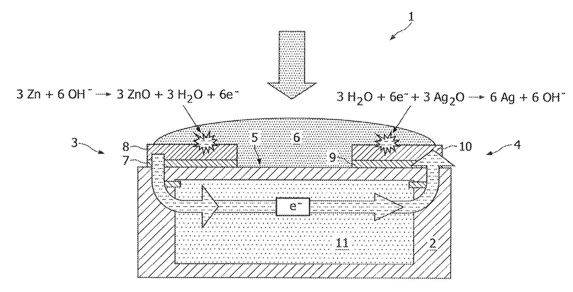
[0020]FIG. 1 shows a schematic cross section of a conventional reserve-type energy source 1. The energy source 1 comprises a substrate 2 onto which a planar negative electrode 3 and a planar positive electrode 4 are deposited. Between both planar electrodes 3, 4 an electrolyte chamber 5 is provided which is filled with a liquid electrolyte 6, such as saliva, in this example of the prior art. The first electrode 3 comprises a (first) current collector 7, and an anode 8 deposited on top of the current collector 7. The second electrode 4 comprises a (second) current collector 9, and a cathode 10 deposited on top of the current collector 9. In this example, the anode 8 is made of zinc, while the cathode 10 is made of silver oxide. By providing the electrolyte chamber 5 with electrolyte 6 an electrochemical reaction will be initiated both at the anode 8 and at the cathode 10 as shown. The electrical energy generated by the energy source 1 is used for powering an electronic device 11 inco...


PUM

PropertyMeasurementUnit
electrochemical energyaaaaaaaaaa
surface areaaaaaaaaaaa
sizeaaaaaaaaaa

Abstract

The invention relates to an electrochemical energy source, comprising a substrate, and at least one cell deposited onto said substrate. The invention also relates to an electronic device, said device comprising at least one electrochemical energy source according to invention, and at least one electronic component electrically connected to said electrochemical energy source.

Description

FIELD OF THE INVENTION[0001]The invention relates to an electrochemical energy source. The invention also relates to an electronic device, said device comprising at least one electrochemical energy source according to invention, and at least one electronic component electrically connected to said electrochemical energy source.BACKGROUND OF THE INVENTION[0002]Reserve batteries are nowadays used to provide on-demand power for a wide variety of applications. These batteries each comprises a two electrodes spaced apart, between which electrodes an electrolyte chamber is present for receiving an externally supplied electrolyte. The main advantage of these batteries is their extremely long shelf life as the electrolyte is only added just prior to use. Very promising applications that might be beneficially powered by this type of battery are, among others, disposable small-scale and cheap electronics like biosensors. In these devices a medium, in particular a liquid, to be examined (blood,...

Claims


Application Information

Patent Timeline
Patent Type & Authority Applications(United States)
IPC IPC(8): H01M4/24H01M4/58H01M4/56H01M4/42H01M4/00H01M8/16
CPCH01M6/34
Inventor NIESSEN, ROGIER ADRIANUS HENRICAMEFTAH, MOHAMMED
Owner KONINKLIJKE PHILIPS ELECTRONICS NV
Why Eureka
Try Eureka