Electrochemical energy source and electronic device provided with such an electrochemical energy source

a technology of electrochemical energy source and electrochemical energy source, which is applied in the manufacture of cell components, current conducting connections, and final products. it can solve the problem of limiting the applicability of known batteries by a large amount, and achieve the effect of sufficient flexibility of energy sources

Inactive Publication Date: 2010-04-22
KONINKLIJKE PHILIPS ELECTRONICS NV
View PDF3 Cites 9 Cited by
  • Summary
  • Abstract
  • Description
  • Claims
  • Application Information

AI Technical Summary

Benefits of technology

[0007]Each flexible element may have a passive character, which means that the flexible element merely be adapted to mutually connect two (or more) electrochemical cells. However, it is preferred that at least one flexible element is provided an additional functionality, in particular a position-selective conducting functionality. To this end, at least one flexible element comprises at least one flexible conductor for connecting respective electrodes of adjacent cells. More preferably, each flexible element comprises multiple flexible conductors for connecting respective electrodes of adjacent cells. In this manner the anodes of all cells can be interconnected in a relatively efficient manner. The same applies for the cathodes of all cells. The conductors may be embedded within the flexible elements. Other parts of the interconnection are preferably made of an electrically insulating material to prevent shot-circuiting of the anode(s) and the cathode(s). The conductors are preferably made of a flexible material to secure the flexible characteristics of the interconnections. In a particular preferred embodiment at least one flexible conductor comprises a conductive polymer or a conductive rubber. Nowadays a wide range of possible conductive polymers and rubbers are available which can be suitably used for interconnecting battery segments. Premix Thermoplastics, for example, manu

Problems solved by technology

A major drawback of the known batteries is that the batteries are substantial

Method used


Image

  • Electrochemical energy source and electronic device provided with such an electrochemical energy source
  • Electrochemical energy source and electronic device provided with such an electrochemical energy source
  • Electrochemical energy source and electronic device provided with such an electrochemical energy source

Examples


Embodiment Construction

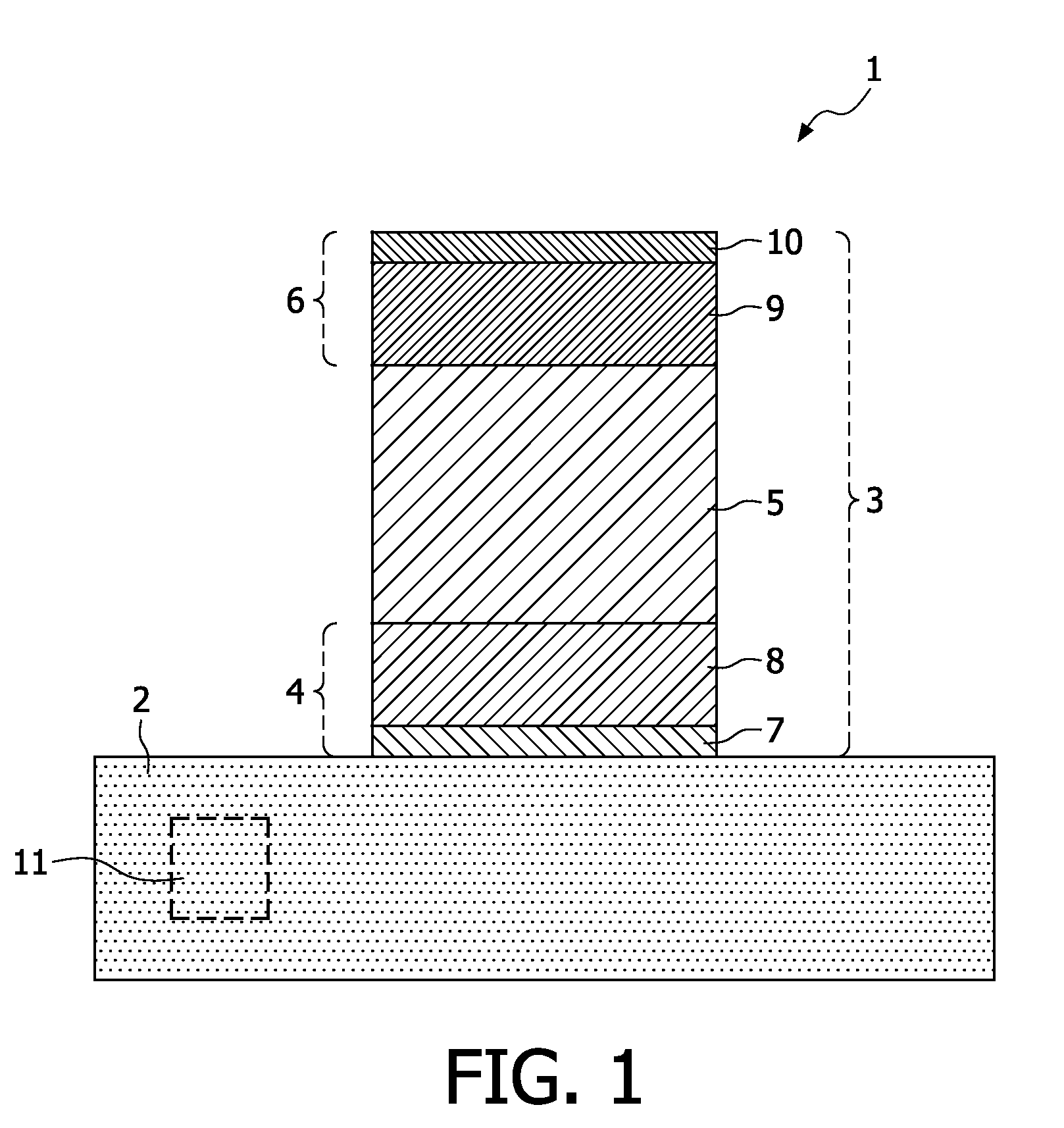
[0018]FIG. 1 shows a schematic cross section of an electrochemical energy source 1 according to the prior art. The known electrochemical energy source 1 comprises a substrate 2 on top of which an electrochemical cell 3 is deposited. The cell 3 comprises a first electrode 4, an electrolyte 5, and a second electrode 6. In this example, the first electrode 4 consists of a first current collector 7, and an cathode 8 deposited on top the first current collector 7, while the second electrode 6 consists of a anode 9, and a second current collector 10 deposited on top of the cathode 9. In this example, the substrate 2 is made from silicon in which one or more electronic components 11 may be embedded, wherein the current collectors 7, 10 are commonly electrically connected to the electronic component(s) 11. Optionally, a reverse stack could be applied wherein the first electrode comprises an anode, and the second electrode comprises a cathode.

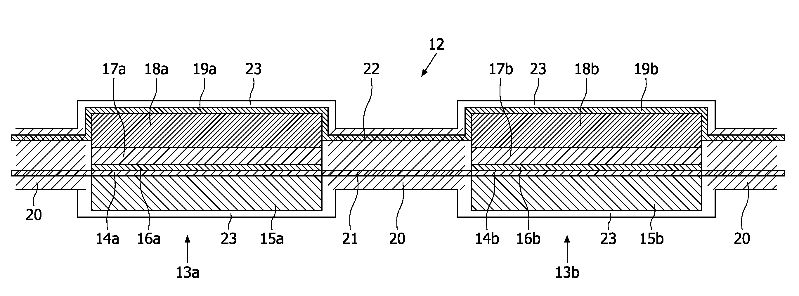
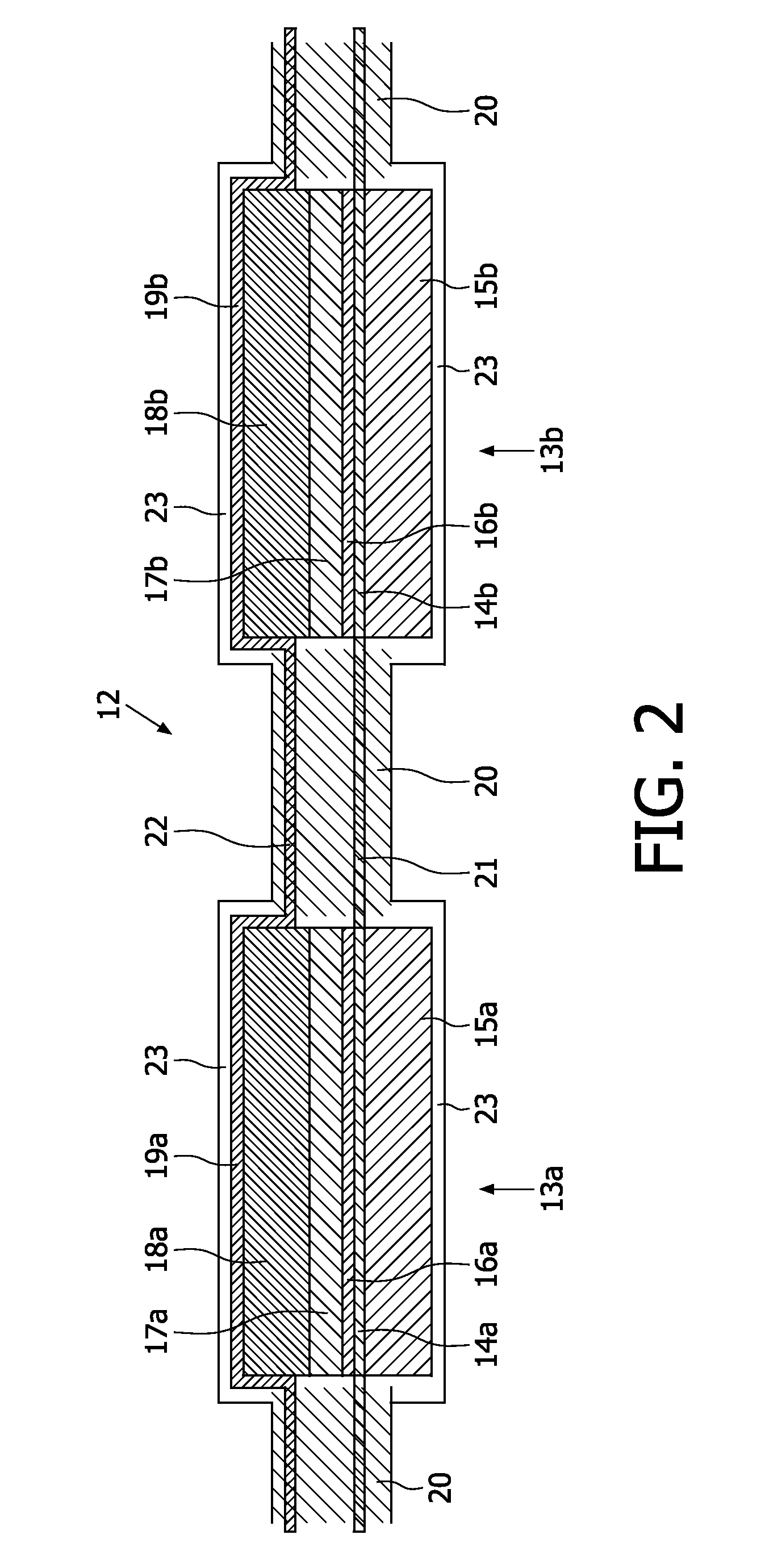
[0019]FIG. 2 shows a schematic cross section of a...


PUM


Abstract

Solid-state batteries, efficiently convert chemical energy into electrical energy and can be used as the power sources for portable-electronics. The invention relates to an improved electrochemical energy source. The invention also relates to an electronic device provided with such an electrochemical energy source. The energy source comprises at least two cells interconnected by means of at least one flexible element. This flexible element may comprise a conductive polymer or a conductive rubber. The electrodes may be provided with cavities (pillars, trenches, slits or holes). A barrier layer may be deposited between the electrodes and their substrate. The energy sources may be used in a “System in Package”.

Description

FIELD OF THE INVENTION[0001]The invention relates to an improved electrochemical energy source. The invention also relates to an electronic device provided with such an electrochemical energy source.BACKGROUND OF THE INVENTION[0002]Electrochemical energy sources based on solid-state electrolytes are known in the art. These (planar) energy sources, or ‘solid-state batteries’, efficiently convert chemical energy into electrical energy and can be used as the power sources for portable electronics. At small scale such batteries can be used to supply electrical energy to e.g. microelectronic modules, more particular to integrated circuits (IC's). An example hereof is disclosed in the international patent application WO 00 / 25378, where a solid-state thin-film micro battery is fabricated directly onto a specific substrate. During this fabrication process the first electrode, the intermediate solid-state electrolyte, and the second electrode are subsequently deposited as a stack onto the su...

Claims


Application Information

Patent Timeline
IPC IPC(8): H01M6/40H01M4/38H01M2/20H01M4/02H01M50/502
CPCH01M6/40H01M2/204H01M50/502Y02P70/50H01M50/50
Inventor OUWERKERK, MARTINNIESSEN, ROGIER ADRIANUS HENRICANOTTEN, PETRUS HENRICUS LAURENTIUS
Owner KONINKLIJKE PHILIPS ELECTRONICS NV
Why Eureka
Try Eureka