Charging system, charger, and battery pack

a charging system and battery technology, applied in the direction of electric vehicles, secondary cell servicing/maintenance, transportation and packaging, etc., can solve the problems of increasing the joule heat generated by a charge current, the battery characteristic is readily deteriorated, and the charge efficiency is significantly deteriorated, so as to reduce the deterioration of the battery characteristic, shorten the charge time of the nonaqueous electrolyte secondary battery, and the effect of hardly deteriorating the battery characteristi

Active Publication Date: 2010-04-29
PANASONIC CORP
View PDF0 Cites 29 Cited by
  • Summary
  • Abstract
  • Description
  • Claims
  • Application Information

AI Technical Summary

Benefits of technology

[0013]An object of the invention is to provide a charging system, a charger, and a battery pack capable of reducing deterioration of the battery characteristic while shortening the charge time of a nonaqueous electrolyte secondary battery.
[0018]In this case, charge is performed at the first current value exceeding the reference current value in the initial stage where the nonaqueous electrolyte secondary battery is charged as it is fed with the charge current and the terminal voltage keeps increasing, that is, when the battery characteristic is hardly deteriorated due to an increase of the charge current. It thus becomes possible to shorten the charge time of the nonaqueous electrolyte secondary battery. In addition, the charge current of the nonaqueous electrolyte secondary battery decreases as the terminal voltage detected by the voltage detection portion increases until the terminal voltage of the nonaqueous electrolyte secondary battery detected by the voltage detection portion has increased to reach the end voltage. The charge current when the terminal voltage of the secondary electrolyte secondary battery has reached the end voltage is therefore consequently reduced, which makes it possible to reduce deterioration of the battery characteristic.

Problems solved by technology

Hence, the lithium-ion secondary battery has a characteristic that the battery characteristic readily deteriorates also when the terminal voltage across the cell nears to the reference voltage Ve (for example, 4.2 V) because it becomes difficult for lithium ions to enter between layers of the negative electrode carbon and the charge efficiency deteriorates significantly, which increases Joule heat generated by a charge current that does not contribute to the charge reaction.
Accordingly, when the reference current value Ie is used as the charge current value I2 of the CC charge, there arises an inconvenience that a charge time is extended because of the synergistic effect of an increase of the capacity and a decrease of the charge current.
However, there are market needs to shorten the charge time on one hand, there are market needs to prolong the cycle life on the other hand.
It is therefore unfavorable to shorten the cycle life in order to shorten the charge time as described above.
When such a charge and discharge cycle is repeated, there is an inconvenience that deterioration of the battery characteristic caused by an overvoltage is accumulated and increased.

Method used


Image

  • Charging system, charger, and battery pack
  • Charging system, charger, and battery pack
  • Charging system, charger, and battery pack

Examples


Embodiment Construction

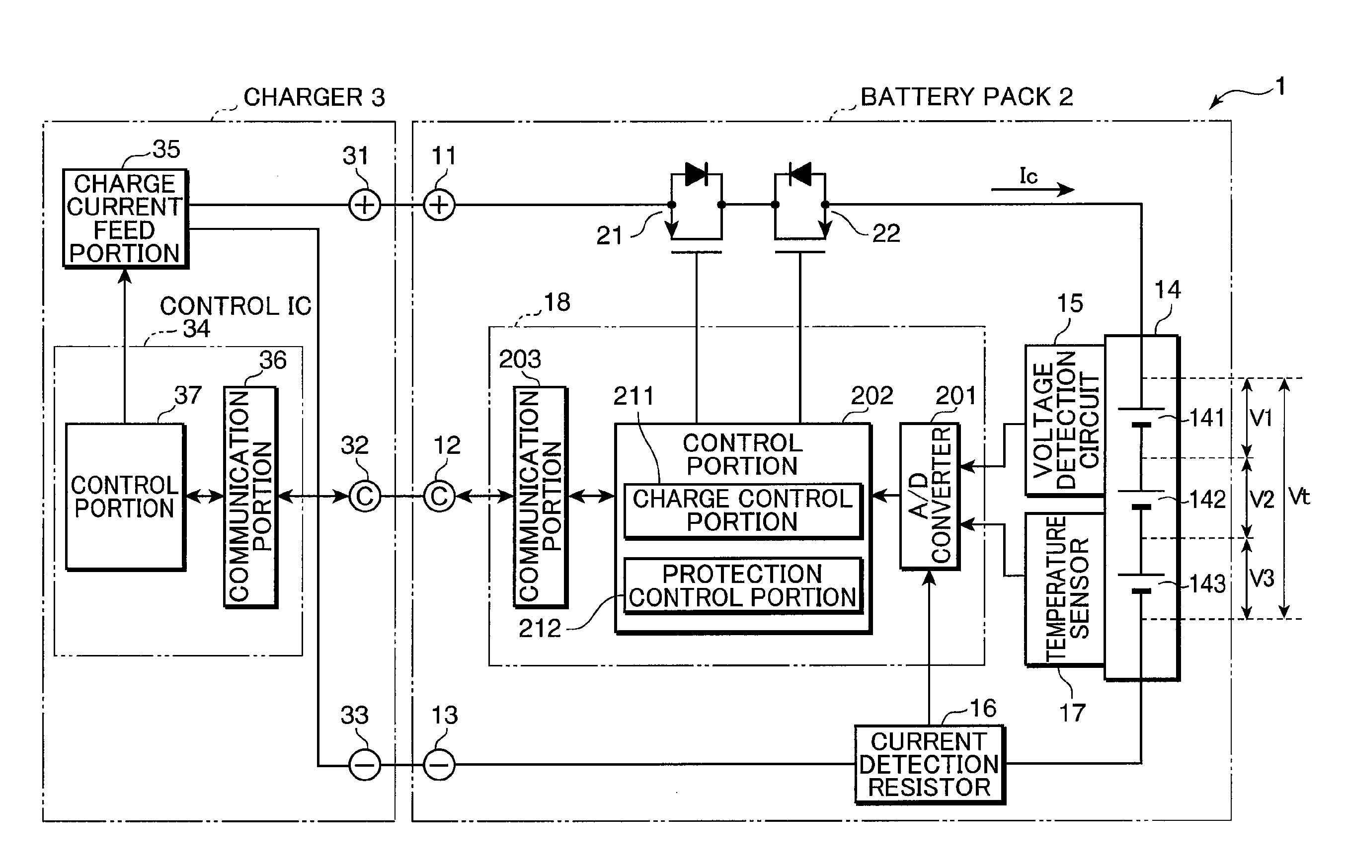
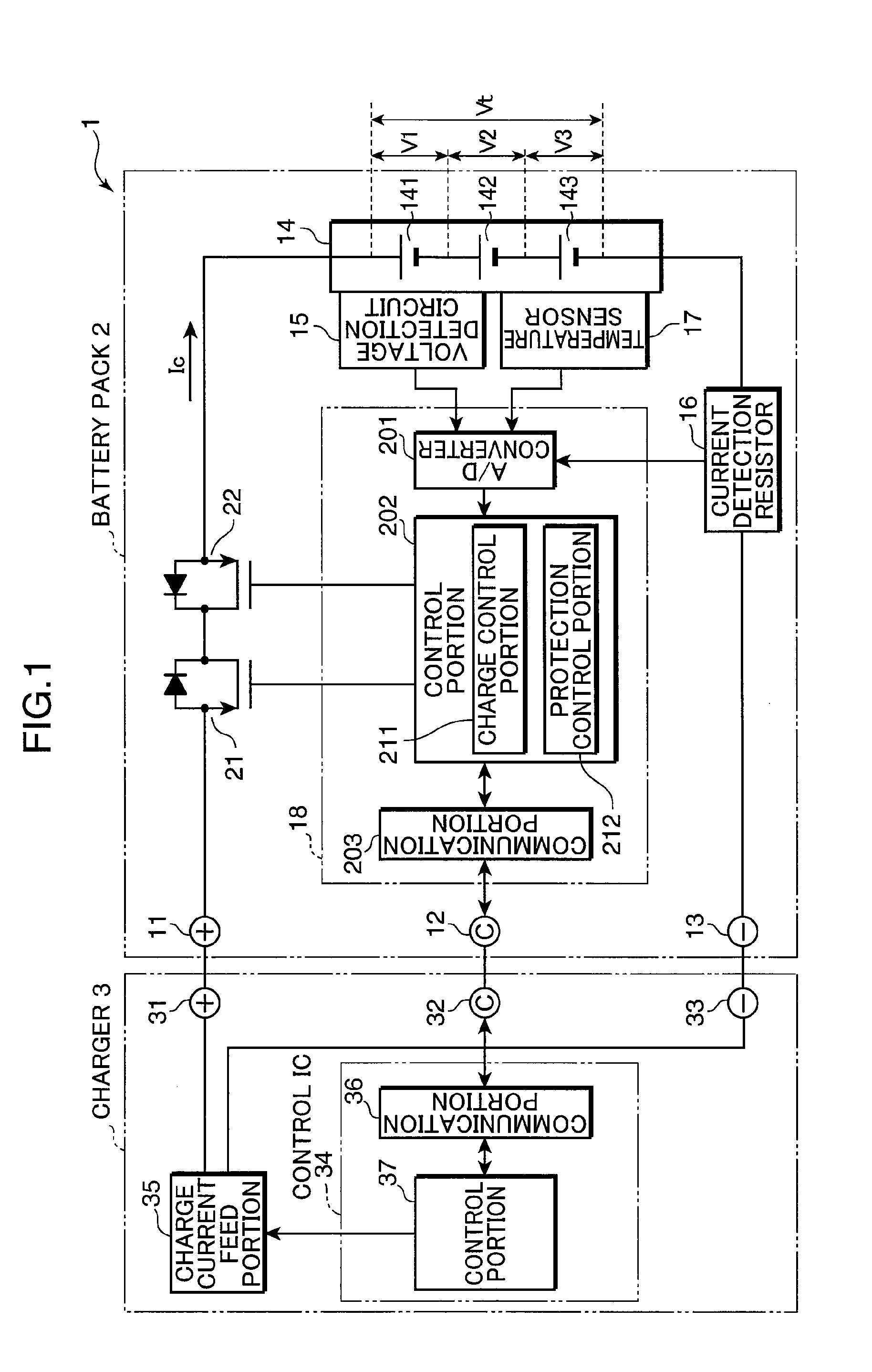
[0024]Hereinafter, one embodiment of the invention will be described with reference to the drawings. Components labeled with the same reference numerals denote the same components and descriptions thereof are omitted. FIG. 1 is a block diagram showing an example of the configuration of a charging system 1 formed of a charger 3 and a battery pack 2 according to one embodiment of the invention. The charging system 1 is formed by providing the battery pack 2 with the charger 3 that charges the battery pack 2. However, an electronic equipment system may be formed by further including an unillustrated load device to which electricity is fed from the battery pack 2. In this case, in contrast to the configuration of FIG. 1 where the battery pack 2 is charged by the charger 3, the battery pack 2 may be attached to the load device so that it is charged via the load device.

[0025]The battery pack 2 includes connection terminals 11, 12, and 13, a set battery 14 (nonaqueous electrolyte secondary...


PUM

PropertyMeasurementUnit
negative electrode potentialaaaaaaaaaa
terminal voltageaaaaaaaaaa
negative electrode potentialsaaaaaaaaaa

Abstract

After the initial current set processing is performed, by which a feed amount of a charge current Ic by a charge current feed portion 35 is set to a first current value I1 exceeding a reference current value Ie preset as a current value of the charge current at which the charge current is flown without causing substantially any deterioration in secondary batteries 141, 142, and 143 while negative electrode potential of the secondary batteries 141, 142, and 143 has dropped to substantially 0 V, the charge current is changed in such a manner that the current value keeps decreasing with an increase of a terminal voltage Vt detected by a voltage detection portion 15 until the terminal voltage Vt detected by the voltage detection portion 15 reaches an end voltage Vf, which is the terminal voltage across a set battery 14 when the negative electrode potentials of the secondary batteries 141, 142, and 143 have dropped to substantially 0 V.

Description

TECHNICAL FIELD[0001]The present invention relates to a charging system, a charger, and a battery pack equipped with a nonaqueous electrolyte secondary battery for charging a nonaqueous electrolyte secondary battery.BACKGROUND ART[0002]FIG. 4 is a view used to describe a charge operation of a secondary battery by CCCV (Constant Current Constant Voltage) charge according to the background art. FIG. 4 shows a case where a nonaqueous electrolyte secondary battery, for example, a lithium-ion secondary battery, is charged and it shows a terminal voltage Vt and a charge current Ic of the lithium-ion secondary battery and the SOC (State of Charge) of the secondary battery.[0003]In the CCCV charge, CC (Constant Current) charge is performed first and then it is switched to CV (Constant Voltage) charge when the terminal voltage Vt across a lithium-ion secondary battery has reached an end voltage Vf, after which a charge current Ic is kept reduced so as to maintain the terminal voltage Vt at t...

Claims


Application Information

Patent Timeline
Patent Type & Authority Applications(United States)
IPC IPC(8): H02J7/00H02J7/04H01M10/44H02J7/10
CPCH01M10/052H01M10/44Y02T10/7011Y02E60/122H02J7/0073H02J7/0071Y02E60/10Y02T10/70
Inventor OTSU, TAKAHISAKIYOHARA, YOSHIKAZU
Owner PANASONIC CORP
Why Eureka
Try Eureka