Projection system for producing attenuation components

Inactive Publication Date: 2010-04-29
KONINKLIJKE PHILIPS ELECTRONICS NV
View PDF2 Cites 10 Cited by
  • Summary
  • Abstract
  • Description
  • Claims
  • Application Information

AI Technical Summary

Benefits of technology

[0003]It is an object of the present invention to provide a projection system for producing attenuation components of projection data of a region of interest, where

Problems solved by technology

But, the final image still comprises a large amount of cor

Method used


Image

  • Projection system for producing attenuation components
  • Projection system for producing attenuation components
  • Projection system for producing attenuation components

Examples


Example

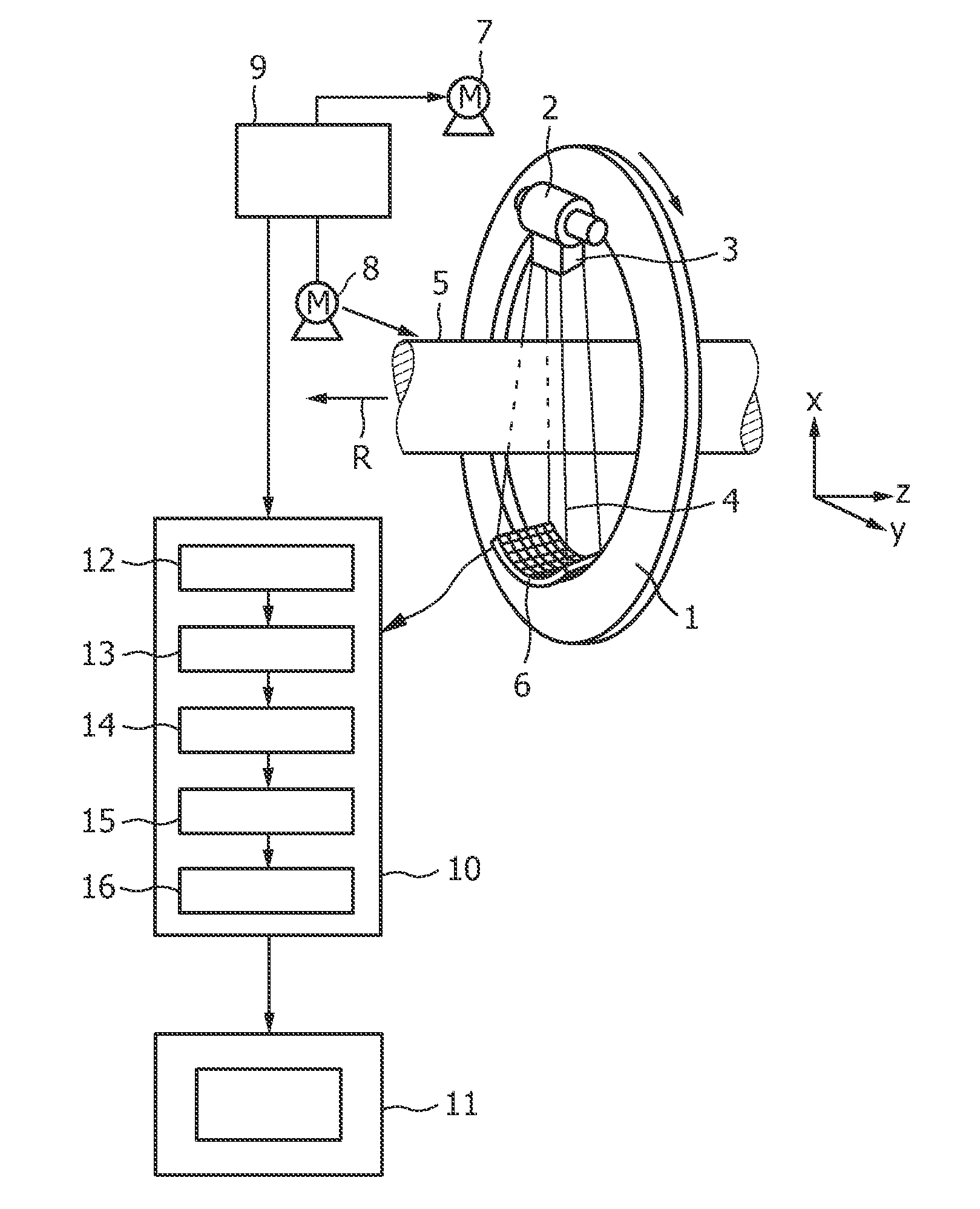
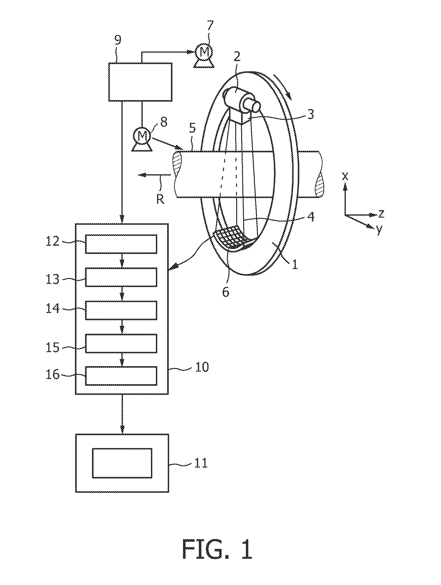
[0035]FIG. 1 shows a projection system being a computed tomography imaging system, which includes a gantry 1, which is capable of rotation about an axes of rotation R which extends parallel to the z direction. A radiation source, which is an X-ray tube 2 in this embodiment, is mounted on the gantry 1. The X-ray tube 2 is provided with a collimator device 3 which forms a conical radiation beam 4 from the radiation emitted by the X-ray tube 2. In other embodiments, the collimator device 3 can be adapted for forming a radiation beam having another shape, for example, having a fan shape.

[0036]The radiation traverses a region of interest of an object (not shown), such as a patient, in a cylindrical examination zone 5. After having traversed the examination zone 5, the X-ray beam 4 is incident on an energy-resolving detection unit 6, in this embodiment a two-dimensional detector, which is mounted on the gantry 1. In another embodiment, the energy-resolving X-ray detection unit can be a on...


PUM


Abstract

The invention relates to a projection system for producing attenuation components of projection data of a region of interest. The projection system comprises a projection data providing unit (1, 2, 6, 7, 8) for providing energy-dependent projection data of the region of interest. The projection system further comprises a calculation unit (12) for calculating different attenuation components generated by different attenuation effects from the energy-dependent projection data, wherein the different attenuation components contribute to the projection data and a transformation unit (13) for transforming the attenuation components such that a correlation of the attenuations components is reduced. The invention relates further to a corresponding projection method and a corresponding computer program.

Description

FIELD OF THE INVENTION[0001]The present invention relates to a projection system, a projection method and a computer program for producing attenuation components of projection data.BACKGROUND OF THE INVENTION[0002]A projection system is, for example, a computed tomography system, which generates projection data and reconstructs an image of a region of interest using the projection data. U.S. Pat. No. 5,115,394 discloses a dual energy-tomography scanning system, which acquires projection data at two different energy levels. Photoelectric and Compton components of the projection data are determined as attenuation components, and a photoelectric image is reconstructed from the photoelectric components and a Compton image is reconstructed from Compton components. The photoelectric and the Compton images are filtered separately such that after the filtered photoelectric image and the filtered Compton image have been combined to a final image, correlated noise in the final image is reduce...

Claims


Application Information

Patent Timeline
IPC IPC(8): G06T5/00
CPCG06T11/005G06T5/002G06T2207/30004G06T2207/10081G06T5/20
Inventor ZIEGLER, ANDYROESSL, EWALDPROKSA, ROLAND
Owner KONINKLIJKE PHILIPS ELECTRONICS NV
Why Eureka
Try Eureka