Heat exchanger, method of manufacturing the same, and egr system

Inactive Publication Date: 2010-05-06
IHI CORP
View PDF9 Cites 10 Cited by
  • Summary
  • Abstract
  • Description
  • Claims
  • Application Information

AI Technical Summary

Benefits of technology

[0037]With the heat exchanger according to the present invention, the partitioning plate is formed of the clad sheet having the clad layer on the entire surface of the flow channel of at least one system, which is exposed in the flow channel, among the fluid channels of at least two systems. For this reason, the surface of the partitioning plate exposed in the flow channel of one system has corrosion resistance and brazing properties. Therefore, it is not necessary to increase the thickness of the partitioning plate in order to ensure corrosion resistance. The heat exchanger, in which the corrosive fluid flows, can be reduced in size, and the performance can be enhanced. Also, it is not necessary to dispose a brazing material on the partitioning plate, and the manufacturing of the heat exchanger can be simplified.
[0038]With the method of manufacturing a heat exchanger according to the present invention, the partitioning plate is made of the clad

Problems solved by technology

(1) Since the partitioning plate is formed thick in order to ensure corrosion resistance, it is difficult to reduce the size and enhance the performance of the heat exchanger.
(2) Since there is a need for a process for disposing the brazing material on the members constituting the flow channel, such as the partitioning plate, the process of manufacturing the heat exchanger is cumbersome and complicated. Also, the performance of the manufactured heat exchanger is difficult to stabilize.
However, it is difficult to apply the powder brazing material mixed with the binder in uniform thickness.
For this reason, it is difficult to dispose th

Method used


Image

  • Heat exchanger, method of manufacturing the same, and egr system
  • Heat exchanger, method of manufacturing the same, and egr system
  • Heat exchanger, method of manufacturing the same, and egr system

Examples


first embodiment

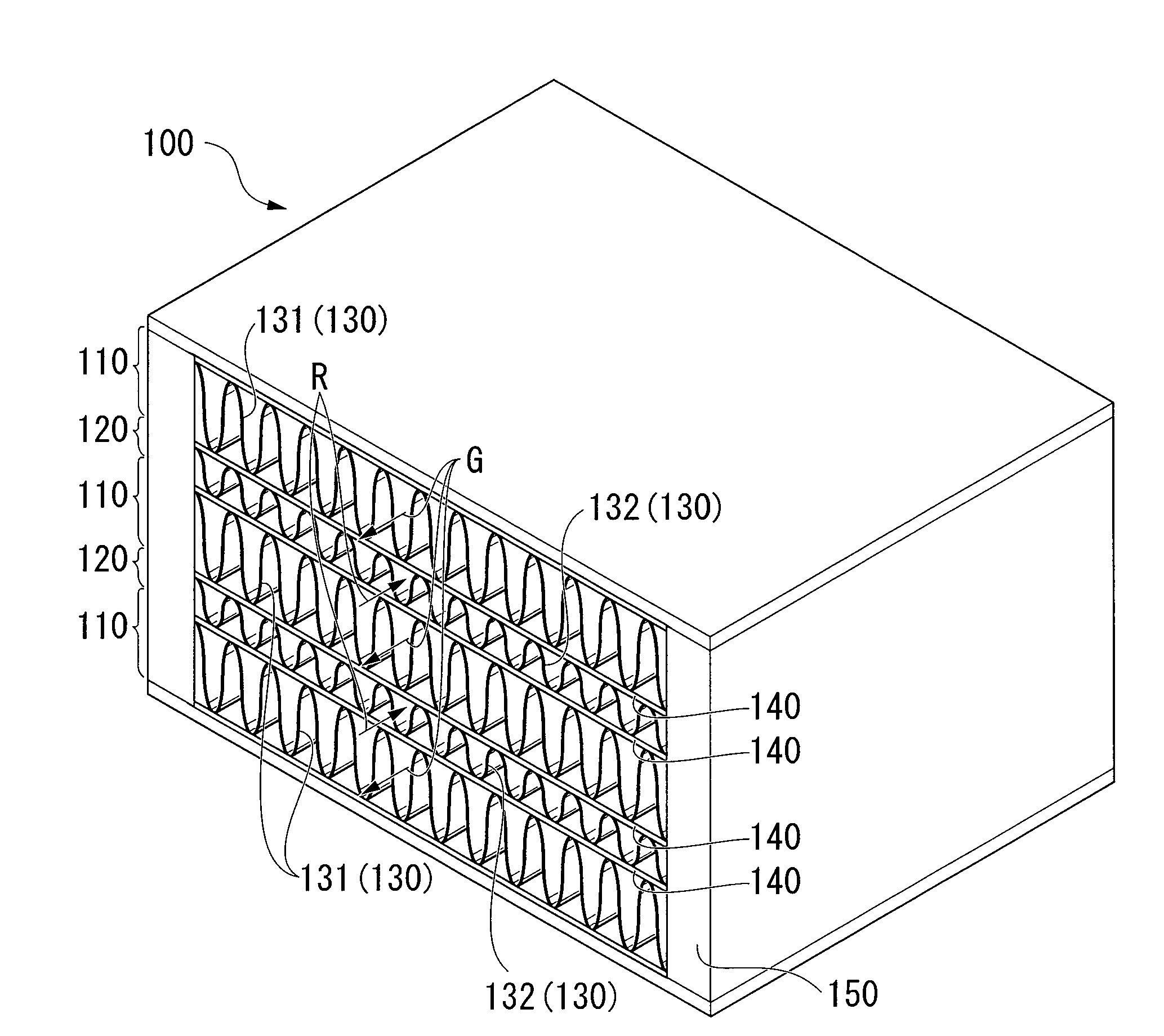
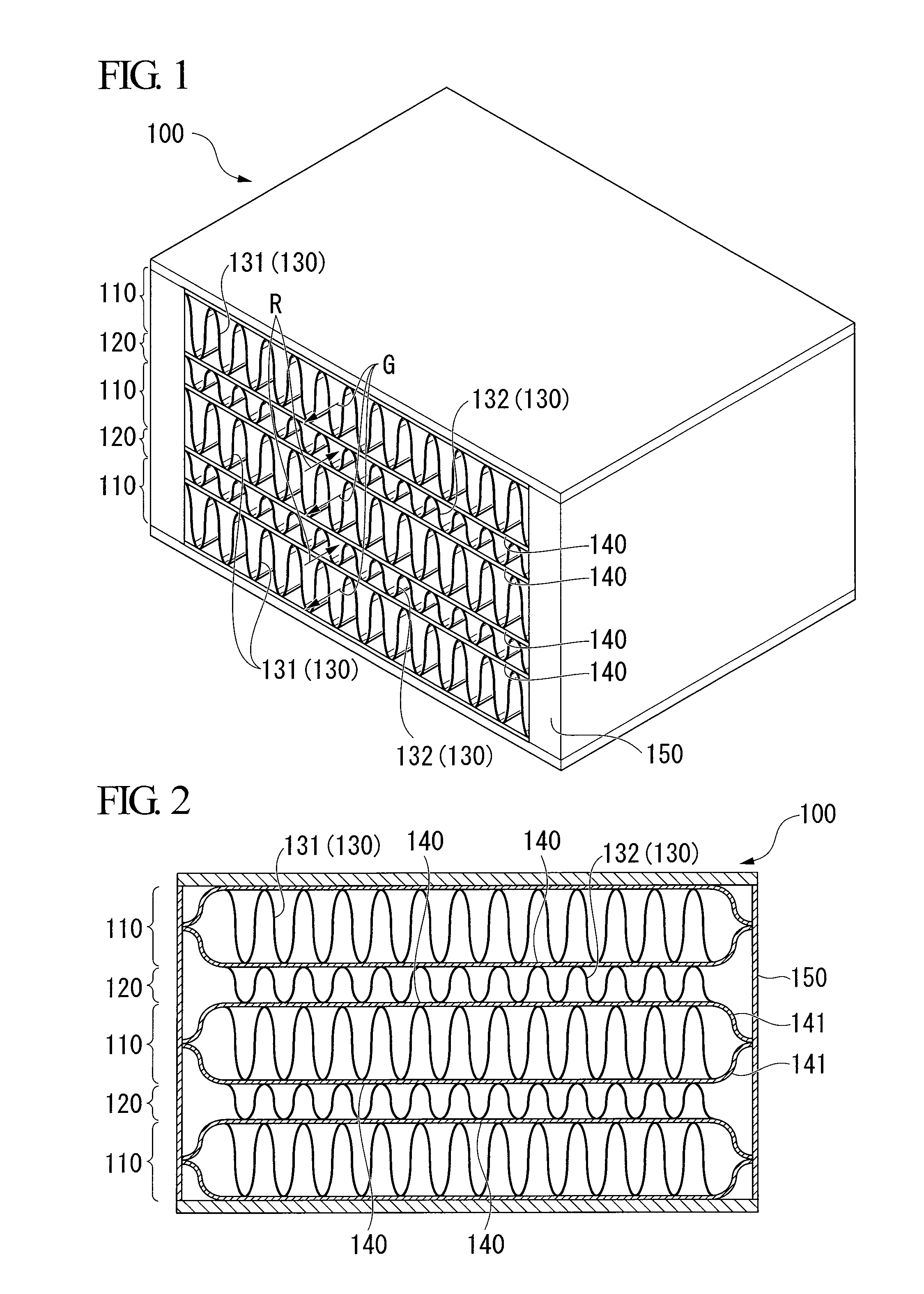
[0071]FIG. 1 is a perspective view schematically illustrating the configuration of a heat exchanger 100 according to a first embodiment. FIG. 2 is a view schematically illustrating a cross section of the heat exchanger 100 according to the first embodiment. As shown in the drawings, the heat exchanger 100 according this embodiment includes corrosive gas flow channels 110 through which corrosive gas G such as combustion exhaust gas of an internal combustion engine flows, and cooling water flow channels 120 through which cooling water R flows, the corrosive gas flow channels and the cooling water flow channels being alternatively stacked on each other in plural layers inside of an external frame 150.

[0072]The corrosive gas flow channel 110 and the cooling water flow channel 120 are partitioned from each other by a partitioning plate 140 which is provided as a boundary of the respective channels. In other words, the plurality of partitioning plates 140 are disposed in the vertical dire...

second embodiment

[0129]Next, a second embodiment of the present invention will now be described. In the description of the second embodiment, the same elements as those of the first embodiment will be omitted or will be described in brief.

[0130]FIG. 10 is a view schematically illustrating a cross section of a heat exchanger 200 according to the second embodiment. As shown in the drawing, the heat exchanger 200 has a configuration in which partitioning plates 210 formed in the shape of a fin are stacked on each other in plural layers inside of the external frame 150. Top portions and bottom portions of the vertically adjacent partitioning plates 210 come in contact with each other, and are brazed to each other to form a plurality of flow channels. The plurality of flow channels are divided into corrosive gas flow channels 220 and cooling water flow channels 230 in a vertically alternating manner. In order to enhance the visibility thereof, the corrosive gas flow channel 220 is shown by hatching in FI...

third embodiment

[0135]Next, an EGR system according to a third embodiment will now be described, the EGR system being equipped with the heat exchanger 100 according to the first embodiment or the heat exchanger 200 according to the second embodiment.

[0136]FIG. 11 is a cross-sectional view schematically illustrating the EGR system 300 according to the present embodiment. As shown in the drawing, the EGR system 300 according to the present embodiment includes an internal combustion engine 310, an intake pipe 320, an exhaust pipe 330, a bypass pipe 340, and an EGR cooler 350.

[0137]The internal combustion engine 310 is one for internally combusting air-fuel mixture therein to obtain a power from the combustion energy, and a diesel engine is employed as the internal combustion engine 310 in this embodiment.

[0138]The intake pipe 320 is a pipe through which combustion air (combustible gas) to be drawn into the internal combustion engine 310 flows, and is connected to the internal combustion engine 310.

[01...


PUM

PropertyMeasurementUnit
Ratioaaaaaaaaaa
Shapeaaaaaaaaaa
Corrosion resistanceaaaaaaaaaa

Abstract

The present invention relates to a heat exchanger including a partitioning plate and flow channels of at least two systems which are partitioned by the partitioning plate, in which the partitioning plate is made of a clad sheet having a base material made of stainless steel or a nickel-based alloy, and a clad layer having brazing properties and corrosion resistance to a corrosive fluid, an entire surface of the base material which is exposed to the flow channel of at least one system being coated by the clad layer. According to the present invention, the heat exchanger, in which the corrosive fluid flows, can be reduced in size, and the performance thereof can be enhanced. Furthermore, it is possible to simplify the manufacturing process of the heat exchanger.

Description

TECHNICAL FIELD[0001]The present invention relates to a heat exchanger which has a flow channel through which a corrosive fluid flows, a method of manufacturing a heat exchanger, and an EGR system including the heat exchanger.[0002]Priority is claimed on Japanese Patent Application No. 2007-115489, filed Apr. 25, 2007, the content of which is incorporated herein by reference.BACKGROUND ART[0003]Due to increased environmental awareness, an EGR (Exhaust Gas Recirculation) system has been proposed in order to suppress generation of NOx in an internal combustion engine (in particular, a diesel engine). With such an EGR system, oxygen concentration in a combustion chamber of the internal combustion engine is decreased by cooling a part of combustion exhaust gas discharged from the internal combustion engine and returning the part to an intake side of the internal combustion engine, thereby trying to reduce NOx.[0004]Such an EGR system includes an EGR cooler (heat exchanger) for cooling a...

Claims


Application Information

Patent Timeline
IPC IPC(8): F28F19/06F28D9/02F28F13/08F02M25/07B21D53/02F01N3/02
CPCB23K1/0012F02B3/06F28D9/0037F28F3/025B23K2101/14F02M26/11F02M26/32Y10T29/4935F28F21/089F28F13/08F28F19/06F28D9/02
Inventor AKIYOSHI, RYOMOCHIZUKI, CHITOSHIYOSHIDA, TAKASHI
Owner IHI CORP
Why Eureka
Try Eureka