Quantum dot electroluminescent device and method for fabricating the same

a quantum dot electroluminescent and electroluminescent device technology, applied in the direction of electroluminescent light sources, chemistry apparatus and processes, and light compositions, can solve the problems of difficult migration of holes throughout the layer, problems with the qd-el device,

Active Publication Date: 2010-05-06
SAMSUNG ELECTRONICS CO LTD
View PDF5 Cites 68 Cited by
  • Summary
  • Abstract
  • Description
  • Claims
  • Application Information

AI Technical Summary

Problems solved by technology

However, a large band offset between the valence band level (about 6.8 eV) of the quantum dots used in the QD-EL device and the HOMO level of the HTL material used in the OLED may result in problems with the QD-EL device.
This may cause problems relating to the turn-on voltage, the operating voltage, the overall efficiency, the carrier injection efficiency, etc. of the QD-EL device.
Further, the use of a HTL material having a HOMO level of 5.4 eV or above causes a large band offset between a HTL and an indium-tin oxide (“ITO”) anode, making the migration of holes throughout the layer difficult.

Method used


Image

  • Quantum dot electroluminescent device and method for fabricating the same
  • Quantum dot electroluminescent device and method for fabricating the same
  • Quantum dot electroluminescent device and method for fabricating the same

Examples


example 1

Fabrication of the QD-EL Device

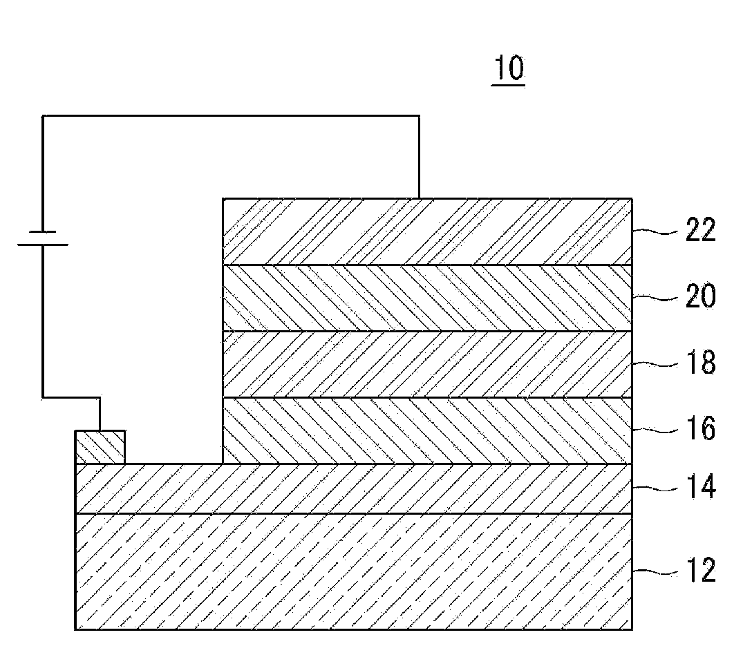
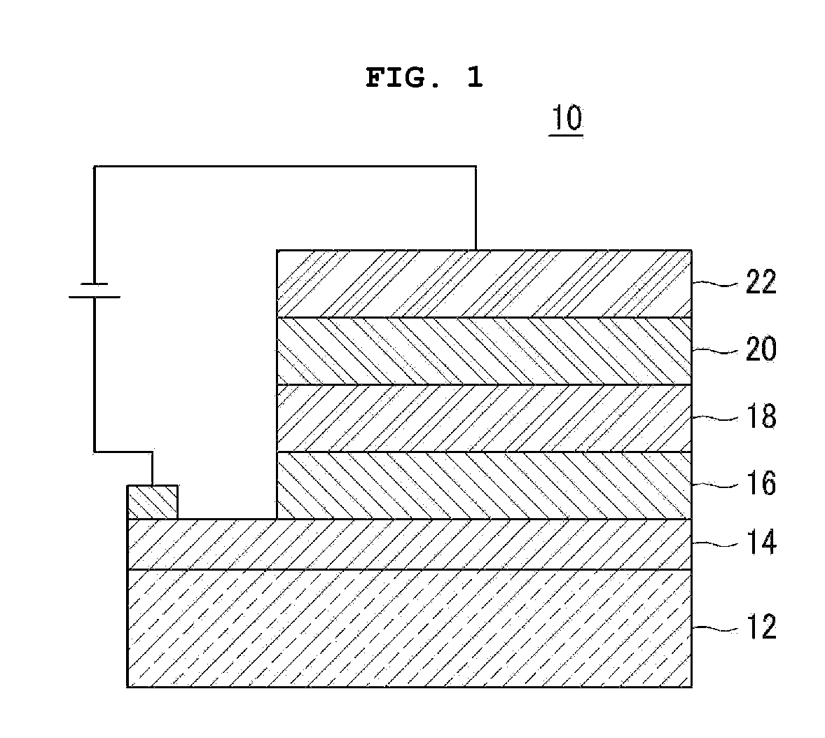
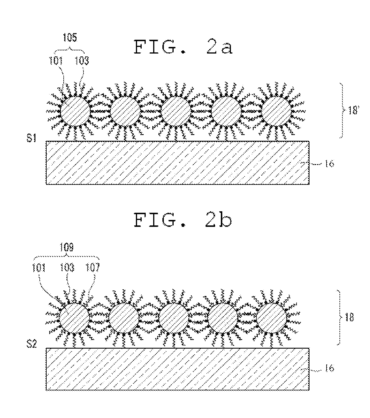
[0098]After an ITO anode is formed on the surface of a glass substrate, a PEDOT HTL is formed on the anode. Poly[(9,9-dioctylfluorenyl-2,7-diyl)-co-(4,4′-(N-(4-sec-butylphenyl))diphenylamine)] (“TFB”) is coated onto the PEDOT HTL that is rotating at a rate of 2,000 rpm inside a glove box. The PEDOT HTL is then thermally treated at 180° C. for 30 minutes to form a 20 nm thick HTL. Then, the colloidal solution containing the QDs as prepared in Preparative Example 1 is spin-coated onto the HTL to form a QD coating. The QD coating is then dipped into the surface modifying composition of Preparative Example 2 at 60° C. for 15 minutes to modify the surface of the HTL. The surface modification gives a QD light-emitting layer. A TiO2 ETL and an Al cathode are formed sequentially on the QD light-emitting layer to complete the fabrication of a QD-EL device.

example 2

Fabrication of QD-EL Device

[0099]After an ITO anode is formed on the surface of a glass substrate, a PEDOT HTL is formed on the anode. Poly[(9,9-dioctylfluorenyl-2,7-diyl)-co-(4,4′-(N-(4-sec-butylphenyl))diphenylamine)] (“TFB”) is coated onto the PEDOT HTL that is rotating at a rate of 2,000 rpm inside a glove box. The PEDOT HTL is then thermally treated at 180° C. for 30 minutes to form a 20 nm thick HTL. Then, the colloidal solution containing the QDs as prepared in Preparative Example 1 is spin-coated onto the HTL to form a QD coating. The QD coating is then dipped into the surface modifying composition of Preparative Example 2 at 60° C. for 15 minutes, and then annealed at 180° C. to modify the surface of the HTL. The surface modification gives a QD light-emitting layer. A TiO2 ETL and an Al cathode are formed sequentially on the QD light-emitting layer to complete the fabrication of a QD-EL device.


PUM

PropertyMeasurementUnit
HOMOaaaaaaaaaa
HOMOaaaaaaaaaa
HOMOaaaaaaaaaa

Abstract

A quantum dot electroluminescent device that includes a substrate, a quantum dot light-emitting layer disposed on the substrate, a first electrode which injects charge carriers into the quantum dot light-emitting layer, a second electrode which injects charge carriers, which have an opposite charge than the charge carriers injected by the first electrode, into the quantum dot light-emitting layer, a hole transport layer disposed between the first electrode and the quantum dot light-emitting layer, and an electron transport layer disposed between the second electrode and the quantum dot light-emitting layer, wherein the quantum dot light-emitting layer has a first surface in contact with the hole transport layer and a second surface in contact with an electron transport layer, and wherein the first surface has an organic ligand distribution that is different from an organic ligand distribution of the second surface.

Description

CROSS-REFERENCE TO RELATED APPLICATION[0001]This application claims priority to Korean Patent application No. 10-2008-109480, filed on Nov. 5, 2008, and all the benefits accruing therefrom under 35 U.S.C. §119, the contents of which in its entirety are herein incorporated by reference.BACKGROUND[0002]1. Field[0003]The following description relates to a quantum dot electroluminescent device and a method for fabricating a quantum dot electroluminescent device. In exemplary embodiments, the quantum dot electroluminescent device has a low turn-on voltage and a low operating voltage while exhibiting high brightness and high luminescence efficiency.[0004]2. Description of the Related Art[0005]A quantum dot is a crystalline semiconductor material having a size of about a few nanometers and consists of about several hundred to about several thousand atoms. The small size of a quantum dot results in a large surface area per unit volume. This allows most of the constituent atoms to be exposed...

Claims


Application Information

Patent Timeline
Patent Type & Authority Applications(United States)
IPC IPC(8): H01L33/00H01L21/28
CPCC09K11/025C09K11/565C09K11/883H01L51/0037H01L51/0039H01L51/502H01L51/5048H05B33/14H10K85/115H10K85/1135H10K50/115H10K50/14C09K11/06
Inventor CHO, KYUNG SANGCHOI, BYOUNG LYONGLEE, EUN KYUNG
Owner SAMSUNG ELECTRONICS CO LTD
Why Eureka
Try Eureka