
Device for conductivity measurement in a controlled environment and method thereof

Inactive Publication Date: 2010-05-06
KENT STATE UNIV
View PDF10 Cites 10 Cited by
  • Summary
  • Abstract
  • Description
  • Claims
  • Application Information

AI Technical Summary

Benefits of technology

[0013]the separator allows the second material to migrate between the environmental medium and the sample.

Problems solved by technology

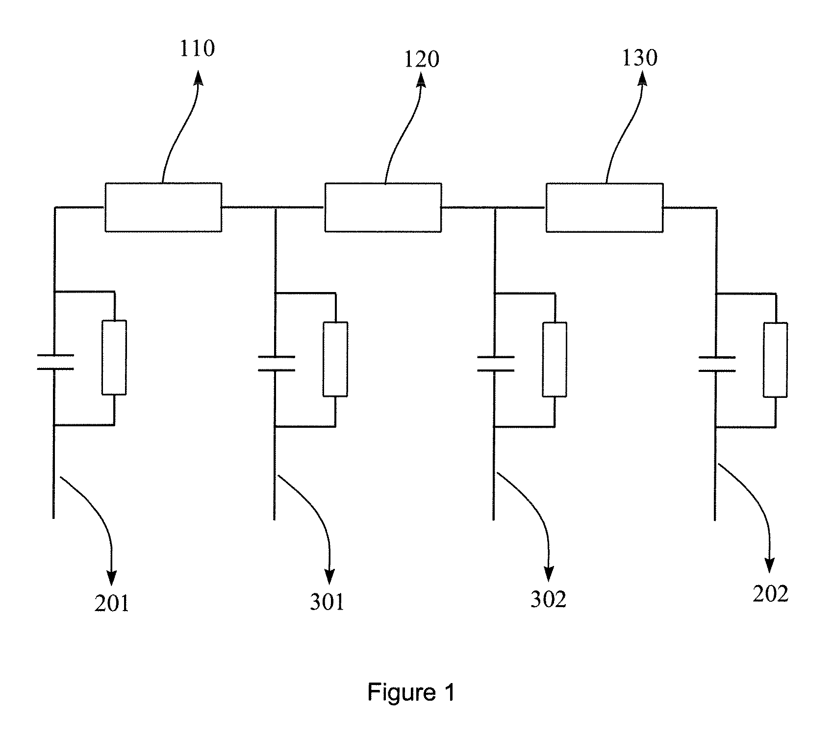
This design does not allow for a quick equilibration between the water / oxygen content in the sample and that in the surrounding, and complicates the analysis of the sample's impedance spectra due to the presence of two interfacial capacitances.
The latter problem is exacerbated by the small thickness of a typical pellet, and, thus, smaller resistance and higher ac frequencies needed for accurate resistance measurements.
This design, however, does not resolve three problems including the interfacial impedance, the humidity equilibration and the loss of contact between the sample and the electrode upon sample shrinking.

Method used


Image

  • Device for conductivity measurement in a controlled environment and method thereof
  • Device for conductivity measurement in a controlled environment and method thereof
  • Device for conductivity measurement in a controlled environment and method thereof

Examples


example 1

A Test Device

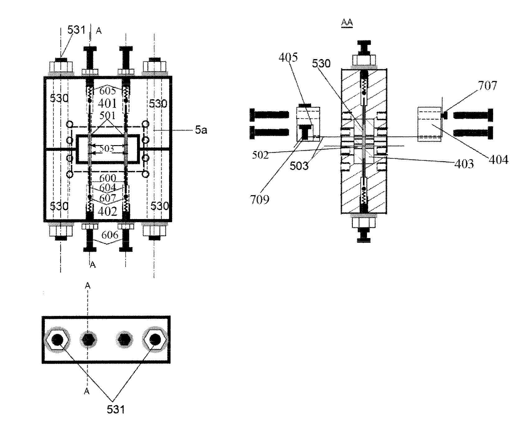
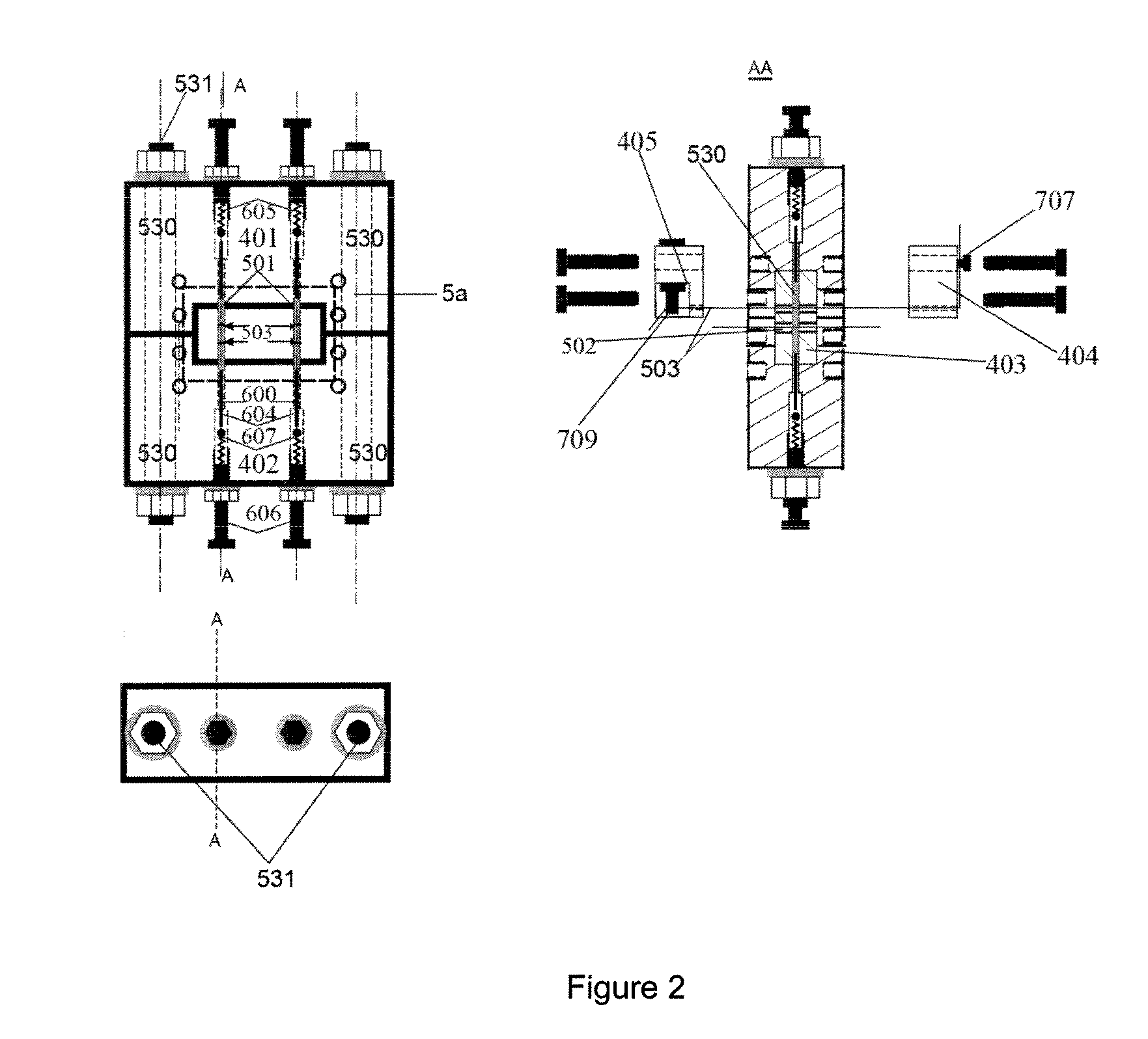
[0065]This example comprises a rectangular box with cylindrical holes drilled in porous zirconium phosphate. One large hole is drilled lengthwise through the box. A sample such as a powder sample was put into this cylindrical channel. Two outer electrodes with a pressure controller such as two spring loaded metal electrodes are inserted into the openings at the ends and pushed against the powder with constant pressure. Two smaller holes are drilled perpendicular in the middle of the box, intersecting the large channel. Inner electrodes such as Pt wires are inserted into these smaller channels and penetrate through the entire width.

[0066]The device consists of three pieces as shown in FIGS. 2 and 3. The top 401 and bottom 402 pieces are identical in shape and made of e.g. polyetherimide (PEI, ULTEM 1000, McMaster #7612K15). A separator such as a sample holder e.g. center piece 403 is made from porous zirconium phosphate (Aremco #502-1550, with μm range pore size and 30% ...

example 2

Conductivity Measurement

[0071]Using the device of Example 1, a comparison between the conductivities of an extruded Nafion film and a Nafion powder at different humidities has been made. The data shows that the conductivity of a powder is several times lower than the conductivity of a film, which is likely due to the porous nature and intergrain resistances in the powder.

[0072]The conductivity of the Nafion film was measured using a four-electrode conductivity clamp (BekkTech BT-110). Both the powder cell and the film clamp were placed into a 1 L custom-made high-pressure environmental chamber (Parr, Moline, Ill.) equipped with a humidity-temperature sensor (Vaisala HMT330), electrical feedthroughs and gas inlet / outlet valves. The chamber temperature can be maintained using a temperature controller (Omega CN 8200) connected to an electrical heating tape (Barnstead international #BIH101-060) and several thermistors positioned inside the chamber. All data reported was obtained at room...

example 3

Comparison Between Two- and Four-Electrode Conductivity Measurements

[0087]The double-layer capacitance at the interface between an electron conductor and an ion conductor imposes restrictions on the ranges of conductivities and frequencies that can be accurately measured using ac impedance spectroscopy. Increasing the ac frequency reduces the effect of the capacitance on the impedance, but in practice the effect of parasitic impedances and of the finite rise time of operational amplifiers makes such measurements inaccurate as can be seen from FIGS. 5 and 6. FIG. 5 shows the conductivity of Nafion 950 powder measured with two (d=20. mm thickness, open circles) and four (d=5.0 mm thickness, solid squares) electrodes at different ac frequencies under experimental conditions of 23° C., 32.1% RH, 300 MPa. and A=7.065 mm2. FIG. 6 shows the dependence of the phase shift between current and voltage on ac frequency in impedance measurements with two (open circles) and four (solid squares) el...


PUM


Abstract

The invention provides a device for measuring the conductivity in a controlled environment and method thereof. The device comprises (i) a sample comprising a first material such as protonic conductor, (ii) an environmental medium comprising a controlled level of a second material such as water vapor, and (iii) a separator such as a sample holder. The separator isolates the sample from the environmental medium; the separator substantially prevents the first material from migrating into the environmental medium; and the separator allows the second material to migrate between the environmental medium and the sample. The invention resolves the problems of e.g. interfacial impedance, humidity equilibration and the loss of contact between the sample and the electrode upon sample shrinking.

Description

[0001]This application claims priority based on the U.S. Provisional Application Ser. No. 61 / 080,018 filed on Jul. 11, 2008, which is incorporated herein by reference in its entirety.BACKGROUND OF THE INVENTION[0002]The present invention is related to a device for measuring the conductivity of materials in a controlled environment and a method thereof. It finds particular application in conjunction with the measurement of a sample such as powder in an environmental medium such as an air / water vapor mixture, and will be described with particular reference thereto. However, it is to be appreciated that the present invention is also amenable to other like applications.[0003]In response to requirements of the fuel cell industry, numerous materials have been studied in recent years as low-humidity proton conductors in different temperature regions. These include acid surface functionalized nanostructures, heteropolyacids, phosphate and / or silicate glasses, hydrogen sulfates and phosphate...

Claims


Application Information

Patent Timeline
IPC IPC(8): G01R1/06
CPCG01N27/043
Inventor TOLMACHEV, YURIY V.GARANIN, EVGENY M.
Owner KENT STATE UNIV
Learn More