Hollow Type Microneedle and Methods for Preparing It

a micro-needle and hollow technology, applied in the field of hollow microneedles, can solve the problems of not being used in the body for analytical material detection and delivery of drugs, affecting the use of various diagnostic techniques and devices, and affecting the use of skin marks, etc., to achieve excellent biocompatibility, increase the drawing speed, and thin and long structure

Active Publication Date: 2010-05-06
IND ACADEMIC CORP FOUND YONSEI UNIV
View PDF12 Cites 16 Cited by
  • Summary
  • Abstract
  • Description
  • Claims
  • Application Information

AI Technical Summary

Benefits of technology

[0008]To achieve the above objects of the present invention, the present invention provides a method of using drawing lithography to fabricate biodegradable solid microneedles. According to the present invention, the entire surface of a substance is first coated with a biodegradable viscous material to be formed into microneedles. Alternatively, only the portion of the substrate, on which microneedles are to be formed, that is, the area that is to be brought into contact with pillars formed on a frame in the desired pattern, is selectively coated with the polymer to form a pattern. The coated material is maintained at a suitable temperature, such that it is not solidified. After the pillars formed on the frame in the desired pattern are brought into contact with the surface of the coated viscous material, the coated viscous material is solidified while it is drawn with the frame. As a result, the coated viscous material forms a structure which has a diameter decreasing from the substrate toward the surface contacting with the frame. The drawing process can be carried out by fixing the substrate and moving the frame upward or downward. Alternatively, it can also be performed by fixing the frame and moving the substrate upward or downward. At this time, solid microneedles having a thin and long structure are fabricated either by increasing the drawing speed, such that a force greater than the tensile strength of the coated material is applied to the coated

Problems solved by technology

Under such circumstances, a needle which may cause pain during its use and leave an external mark on the skin has hindered the use of such various diagnosing techniques and devices.
However, since the solid silicon microneedle according to this method was not a hollow structure, it could not be used for analytical material detection in the body and delivery of drugs.
As such, various hollow silicon microneedles have been developed, but these caused pain upon penetration of the skin owing to their large diameter, and were not efficient in extracting internal analytical materials from the body and drug delivery owing to their length of 500□.
However, the hollow metal micro

Method used


Image

  • Hollow Type Microneedle and Methods for Preparing It
  • Hollow Type Microneedle and Methods for Preparing It
  • Hollow Type Microneedle and Methods for Preparing It

Examples


example 1

Preparation of Solid Type Microneedle

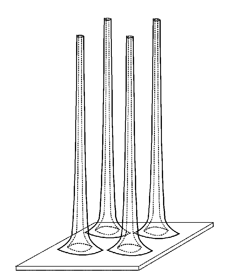
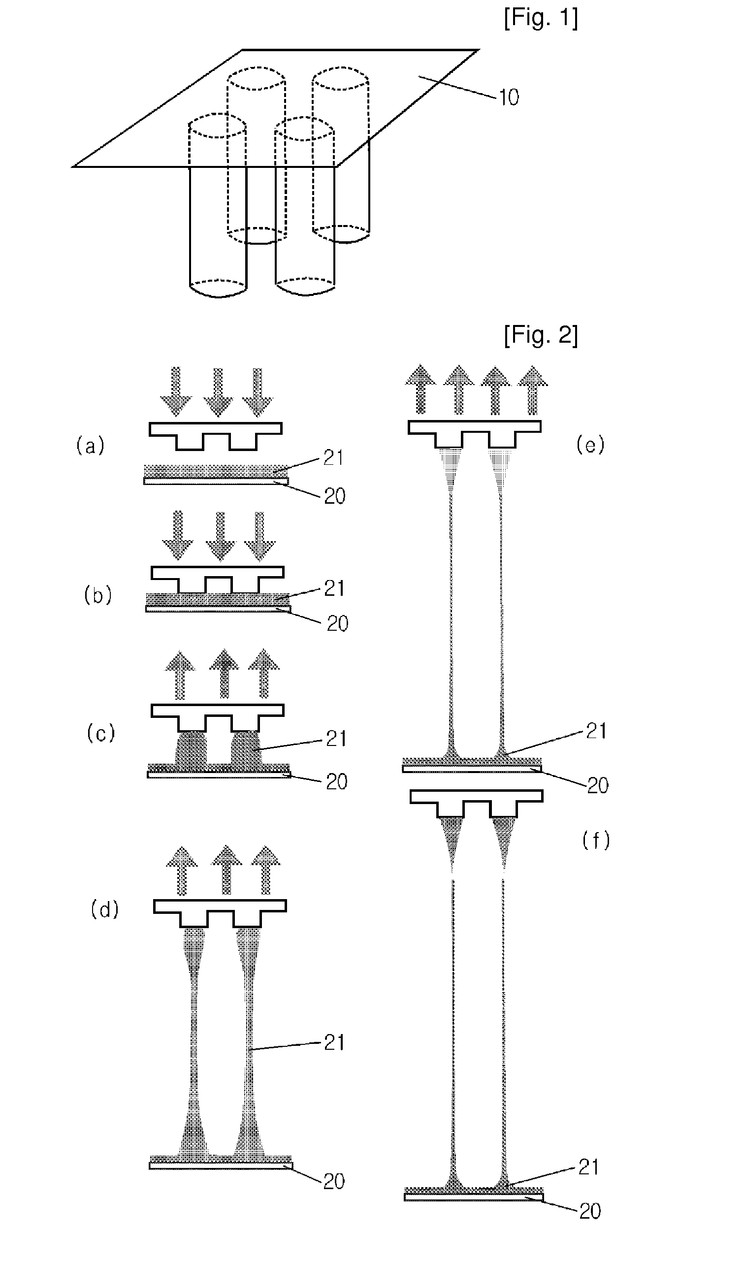
[0031]SU-8 2050 photoresist (commercially purchased from Microchem) having a viscosity of 14,000 cStwas used to fabricate solid microneedles. For this purpose, SU-8 2050 was coated on a flat glass panel to a certain thickness, and it was maintained at 120° C. for 5 minutes to maintain its flowing properties. Then, the coated material was brought into contact with a frame having 2×2 pillar patterns formed thereon, each pillar having a diameter of 200 □ (See FIG. 1). The temperature of the glass panel was slowly lowered to 95-90° C. over about 5 minutes to solidify the coated SU-8 2050 and to increase the adhesion between the frame and the SU-8 2050. Then, while the temperature was slowly lowered from 95-90° C., the coated SU-8 2050 was drawn at the speed of 1 58 / s for 60 minutes using the frame which adhered to the coated SU-8 2050 (See FIG. 2). After 60 minutes of drawing, solid microneedles, each having a length of about 3,600□, were formed. Sub...

example 2

Preparation of Hollow Microneedle

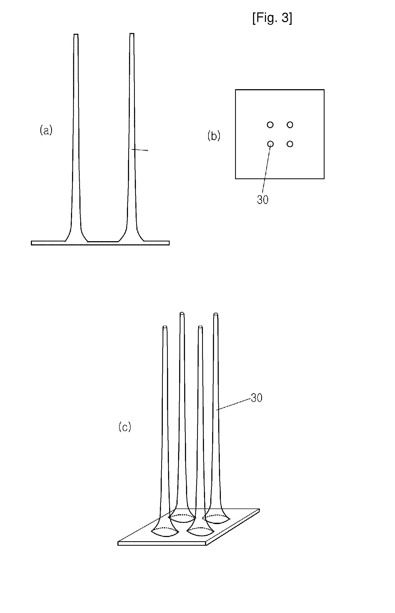
[0032]Three layers of Ti-Cu-Ti (100□-300□-100□) were deposited on the SU-8 solid type microneedle (30) (FIG. 4a) prepared from Example 2 by sputtering (FIG. 4b).

[0033]As another example, an Ag layer was deposited on the SU-8 solid type microneedle (30) (FIG. 4a), when a sliver mirror reaction was used (FIG. 4b). Next, the upper end part of the deposited solid type microneedle was protected with enamel or SU-8 2050 (See, FIGS. 4c to 4f). The enamel or SU-8 2050 treatment to the upper end part is to prevent the upper end part from being metal-plated in the subsequent step. Then, the surface of the solid type microneedle, the upper end part of which was protected, was electroplated with nickel (FIG. 5a). The Ni electroplating was carried out at 0.206 □ / min. per 1 A / d for 60 minutes, resulting in a plated metal thickness of 10□ and an outer diameter of 50□. The plating metal thickness was controlled depending on the plating time. As another example, the ...


PUM

PropertyMeasurementUnit
Lengthaaaaaaaaaa
Diameteraaaaaaaaaa

Abstract

Disclosed herein are hollow microneedles and a fabrication method thereof. The microneedles are small in diameter and are long and hard enough to pass through the stratum corneum. Therefore, the hollow microneedle of the present invention can be used in blood sampling or drug injection through the skin.

Description

TECHNICAL FIELD [0001]The present invention relates to a hollow microneedle and a fabrication method thereof.BACKGROUND ART[0002]Generally, needles are used in sampling of analytical materials such as blood, for diagnosis of various diseases, or drug injection into the body. With the development of various diagnosing techniques and diagnosing chips, the demand for extracting analytical materials from the body has increased. Under such circumstances, a needle which may cause pain during its use and leave an external mark on the skin has hindered the use of such various diagnosing techniques and devices. As a result, microspikes and solid microneedles which are penetration type needles and hollow microneedles which are open tip type needles have been suggested.[0003]Unlike conventional neddles, the microneedles should not cause pain when they penetrate the skin, and for such painless skin penetration, the diameter of the upper end part of the needle is a matter to be considered. The m...

Claims


Application Information

Patent Timeline
IPC IPC(8): A61M5/00B05D7/00
CPCA61M37/0015A61M2037/003A61M2037/0053A61M37/00
Inventor JUNG, HYUNG ILLEE, KWANG
Owner IND ACADEMIC CORP FOUND YONSEI UNIV
Why Eureka
Try Eureka