

Cathodes for microbial electrolysis cells and microbial fuel cells
a fuel cell and electrolysis cell technology, applied in cell components, electrochemical generators, manufacturing tools, etc., can solve the problems of limited performance of current cathodes and mfcs, and the need for expensive materials for current cathodes, so as to enhance an electrical potential
- Summary
- Abstract
- Description
- Claims
- Application Information
AI Technical Summary
Benefits of technology
Problems solved by technology
Method used
Image

Examples
example 1
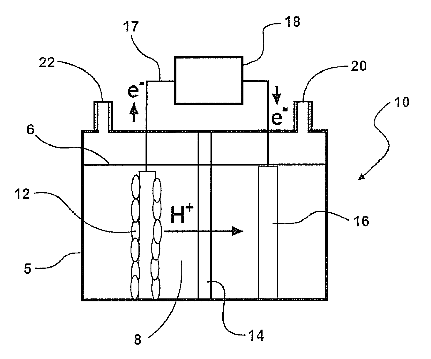
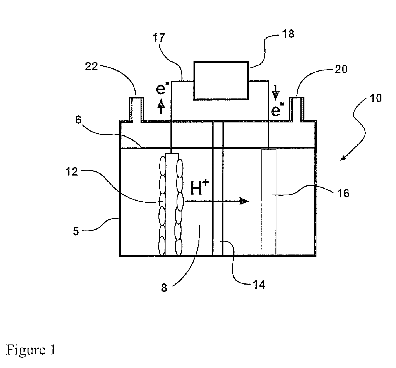
[0164]Cathodes
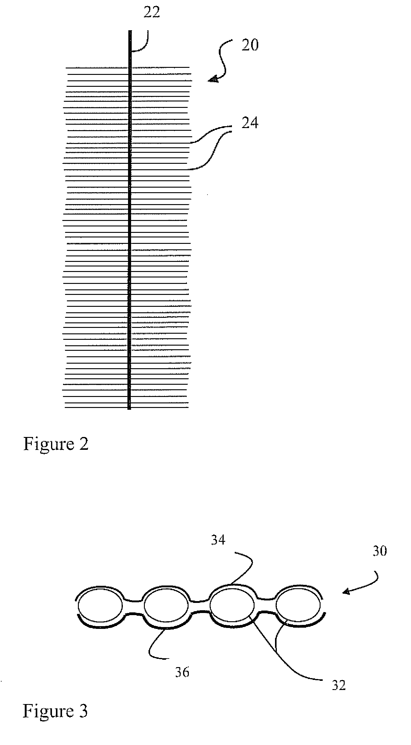
[0165]SS brush cathodes (Gordon Brush Mfg Co., Inc., Commerce, Calif.) were made of grade 304 SS, which has the composition: 0.08% C, 2% Mn, 0.045% P, 0.03% S, 1% Si, 18-20% Cr, and 8-11% Ni (balance Fe) (ASTM. Document number A 959-07. Standard guide for specifying harmonized standard grade compositions for wrought stainless steels. Table 1. Chemical Composition Limits, %., Oct. 4, 2008). The bristles (0.008 cm diameter) were wound into a twisted SS core (0.20 cm diameter) using an industrial brush manufacturing machine. The brushes were 2.5 cm long and 2.5 cm in diameter. On the basis of the mass and estimated surface area of the bristles, each brush (100% loading case) had 310 cm2 of surface area, producing 2500 m2 / m3-brush volume (95% porosity), for a specific surface area of AS=650 m2 / m3 of reactor volume. In some tests, brushes with reduced bristle loadings of 50%, 25%, and 10% were used, with surface areas of 160 cm2 (AS=340 m2 / m3), 110 cm2 (AS=240 m2 / m3), and m...
example 2
[0183]Hydrogen production in an MEC using a cathode made of stainless steel, nickel, and stainless steel with a high nickel content. Single-chamber MEC reactors were constructed from polycarbonate cut to produce a cylindrical chamber 4 cm long by 3 cm in diameter (empty bed volume of 28 mL). The anodes were ammonia treated graphite brushes, 25 mm diameter×25 mm length, 0.22 m2 surface area. Ammonia treatment of the graphite brushes was accomplished as described in Example 1.
[0184]Reactors were inoculated with the anode solution from another acetate-fed MEC reactor that had been running for over 1 year and acetate (1 g / L) in medium. The medium used was a 50 mM phosphate buffer solution (4.58 g / L Na2HPO4 and 2.45 g / L Na2HPO4·H2O; pH=7.0), 0.31 g / L NH4Cl, 0.13 g / L KCl, and trace vitamins and minerals.
[0185]Cathodes of stainless steel alloys 304, 316, 420 and A286 or nickel alloys 201, 400, 625 and HX were made by cutting sheet metal (McMaster-Carr, IL) into 3.8 cm diameter disks. Metal...
example 3
[0204]Hydrogen production in an MEC using a cathode with electrochemically deposited nickel oxide. The same reactor and conditions were examined as described in Example 2, except here a nickel oxide catalyst was deposited through cathodic electrodeposition onto a sheet metal support using a 12.9 cm2 nickel foam anode. Electrodeposition was achieved by applying 20V at ˜2 A for 30 s (1696 power source, B&K Precision, CA) in a solution containing 12 mM Ni SO4 and 20 mM (NH4)2SO4 at a pH=2.0 by adding H2SO4. Cyclic voltammetry (CV) scans were performed on the electrodeposited metal to ensure consistent electrodeposition. Tests were conducted in a Lexan cell using a 50 mM phosphate buffer, a Ag / AgCl reference electrode, and a platinum counter electrode (3 cm×5 mm) with a scan range of 0.2 to −1.2V and a scan rate of 3 mVs−1. Consistent electrodeposition was confirmed as all nickel oxide cathodes had similar hydrogen evolution potentials between −0.65 and −0.70V. The electrodes were subse...
PUM
| Property | Measurement | Unit |
|---|---|---|
| Temperature | aaaaa | aaaaa |
| Electric potential / voltage | aaaaa | aaaaa |
| Volume | aaaaa | aaaaa |
Abstract
Description
Claims
Application Information