Semiconductor light emitting apparatus including elongated hollow wavelength conversion tubes and methods of assembling same

Active Publication Date: 2010-05-20
IDEAL IND LIGHTING LLC
View PDF28 Cites 50 Cited by
  • Summary
  • Abstract
  • Description
  • Claims
  • Application Information

AI Technical Summary

Benefits of technology

[0010]Various other embodiments of the invention can provide an elongated hollow wavelength conversion tube that is oriented relative to the semiconductor light emitting device, so as to provide a longer path length through the elongated wavelength conversion tube wall for light that is emitted by the semiconductor light emitting device that does not strike the wavelength conversion material embedded therein without increasing

Problems solved by technology

While it may be possible to achieve fairly high luminous efficacy and/or color rendering with such lamps, wav

Method used


Image

  • Semiconductor light emitting apparatus including elongated hollow wavelength conversion tubes and methods of assembling same
  • Semiconductor light emitting apparatus including elongated hollow wavelength conversion tubes and methods of assembling same
  • Semiconductor light emitting apparatus including elongated hollow wavelength conversion tubes and methods of assembling same

Examples


Example

[0026]The present invention now will be described more fully with reference to the accompanying drawings, in which various embodiments are shown. This invention may, however, be embodied in many different forms and should not be construed as limited to the embodiments set forth herein. Rather, these embodiments are provided so that this disclosure will be thorough and complete, and will fully convey the scope of the invention to those skilled in the art. In the drawings, the size and relative sizes of layers and regions may be exaggerated for clarity. Like numbers refer to like elements throughout.

[0027]The terminology used herein is for the purpose of describing particular embodiments only and is not intended to be limiting of the present invention. As used herein, the singular forms “a,”“an” and “the” are intended to include the plural forms as well, unless the context clearly indicates otherwise. It will be further understood that the terms “comprising”, “including”, “having” and...


PUM


Abstract

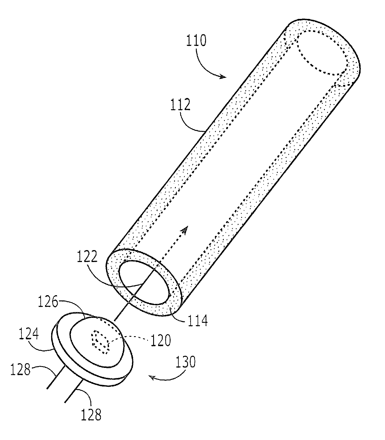
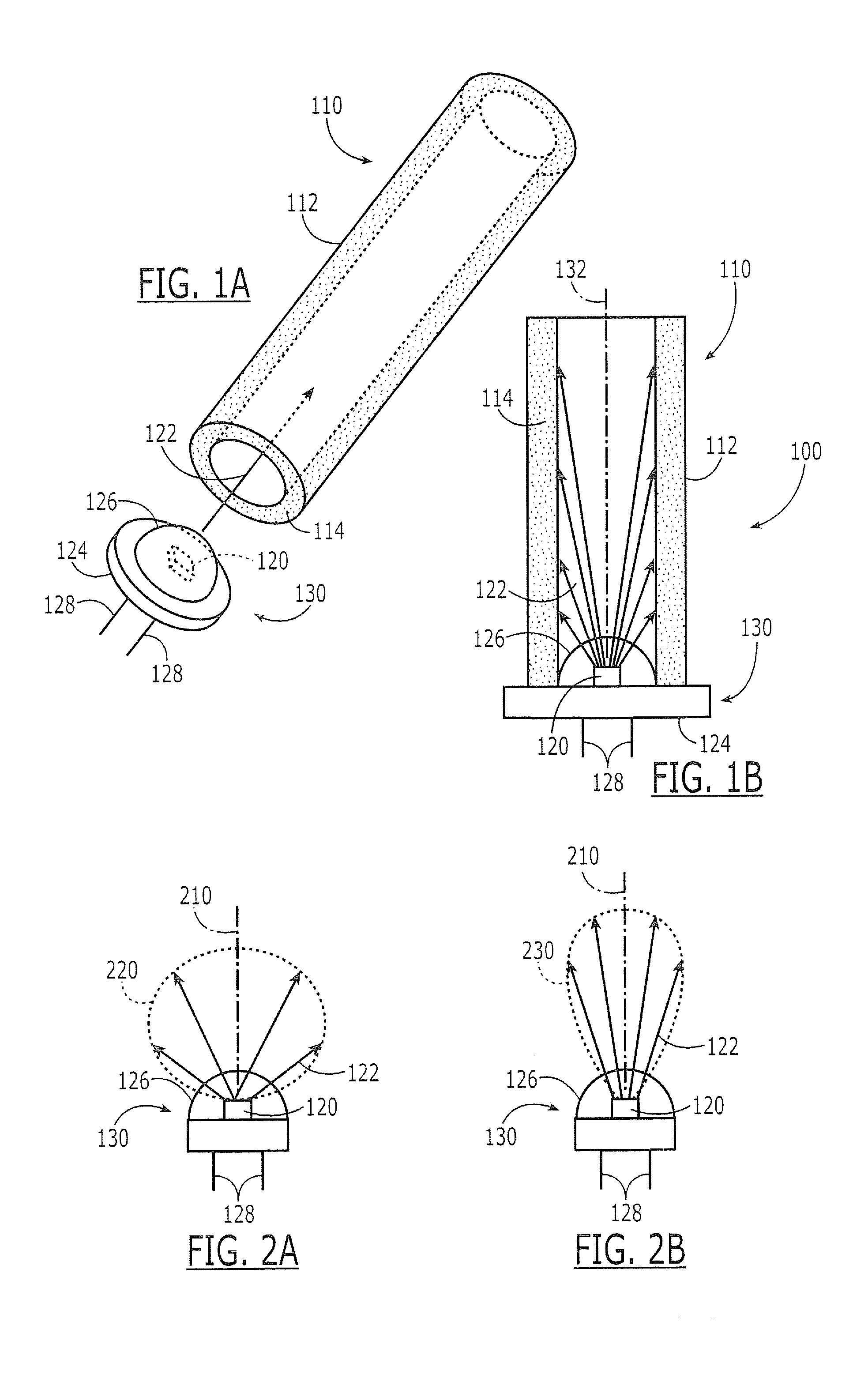
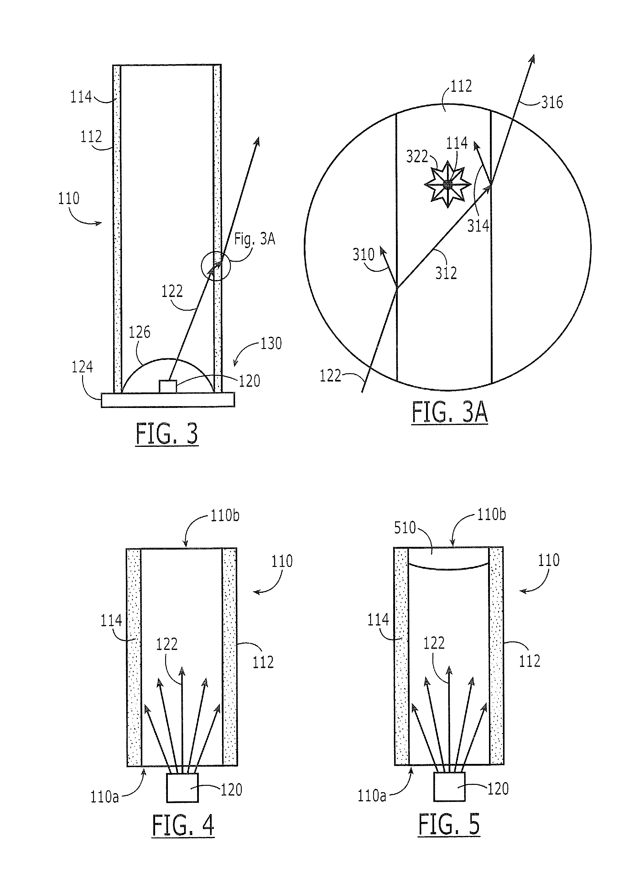
A semiconductor light emitting apparatus includes an elongated hollow wavelength conversion tube that includes an elongated wavelength conversion tube wall having wavelength conversion material, such as phosphor, dispersed therein. A semiconductor light emitting device is oriented to emit light inside the elongated hollow wavelength conversion tube to impinge upon the elongated wavelength conversion tube wall and the wavelength conversion material dispersed therein. The elongated hollow wavelength conversion tube may have an open end, a crimped end, a reflective end, and/or other configurations. Multiples tubes and/or multiple semiconductor light emitting devices may also be used in various configurations. Related assembling methods are also described.

Description

BACKGROUND OF THE INVENTION[0001]This invention relates to light emitting apparatus and methods of assembling and operating same, and more particularly to semiconductor light emitting apparatus and methods of assembling and operating same.[0002]Semiconductor light emitting devices (“LEDs”), such as light emitting diodes and laser diodes, are widely known solid-state lighting elements that are capable of generating light upon application of voltage thereto. Light emitting devices generally include a p-n junction, an anode ohmic contact for the p-type region of the device, and a cathode ohmic contact for the n-type region of the device. The device may be formed on a substrate, such as a sapphire, silicon, silicon carbide, gallium arsenide, gallium nitride, etc., substrate, or the device may not include a substrate. The semiconductor p-n junction may be fabricated, for example, from silicon carbide, gallium nitride, gallium phosphide, aluminum nitride and / or gallium arsenide-based mate...

Claims


Application Information

Patent Timeline
IPC IPC(8): H01S5/02H01L23/00
CPCF21K9/00F21K9/52F21Y2101/02G02B6/0003G02B6/001F21V29/70G02B6/005G02B6/0096F21V15/01F21K9/56G02B6/0035F21K9/61F21K9/64F21Y2115/10G02B6/00G02B6/0001
Inventor HUSSELL, CHRISTOPHER P.EDMOND, JOHN ADAM
Owner IDEAL IND LIGHTING LLC
Why Eureka
Try Eureka