High resolution surface plasmon resonance sensor and sensor system thereof

a surface plasmon resonance and sensor technology, applied in the field of biochemical sensors, can solve the problems of poor thermal, chemical and mechanical stability of ag, inferior biocompatibility, poor optical properties, etc., and achieve the effect of significantly enhancing the stability of the sensor and remarkable improvement of the sensor resolution

Inactive Publication Date: 2010-05-27
KOREA INST OF SCI & TECH
View PDF5 Cites 22 Cited by
  • Summary
  • Abstract
  • Description
  • Claims
  • Application Information

AI Technical Summary

Benefits of technology

[0012]The present disclosure provides a high-resolution surface plasmon resonance sensor capable of decreasing a linewidth of the reflectance dip curve due to the surface plasmon resonance, and increasing the electric field amplitude near the metal film surface, thereby enhancing the responsivity to an environmental change, especially, in a localized region to the metal surface, extending a dynamic range, and simultaneously, enhancing stability of the sensor.
[0015]When the surface plasmon resonance sensor according to the embodiment of the disclosure is used, there are advantages in that due to a sharp resonance curve and an effect of local electric field enhancement, the resolution of sensor is remarkably improved to detect a small change in refractive index of a surrounding medium, and especially sensitive to a change in a local environment adjacent to a metal layer surface, and the stability of sensor is significantly enhanced as well.

Problems solved by technology

However, there are problems in that Ag has poor thermal, chemical and mechanical stabilities, and inferior biocompatibility.
However, the optical properties are worse than those of Ag.
It has been known that the conventional surface plasmon resonance sensor which mainly uses a single Au layer with a thickness of about 50 nm has a limitation in resolution.
With limited available metals, most of current efforts have been concentrated on decreasing the linewidth of the resonance curve.
However, since these methods still have problems in stability and resolution, a surface plasmon resonance sensor with further enhanced stability and resolution is required.

Method used


Image

  • High resolution surface plasmon resonance sensor and sensor system thereof
  • High resolution surface plasmon resonance sensor and sensor system thereof
  • High resolution surface plasmon resonance sensor and sensor system thereof

Examples


Embodiment Construction

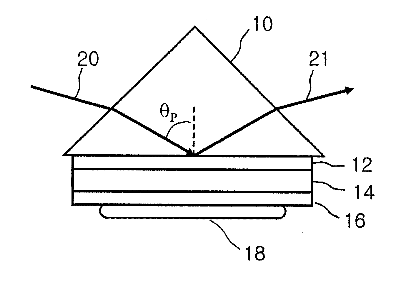
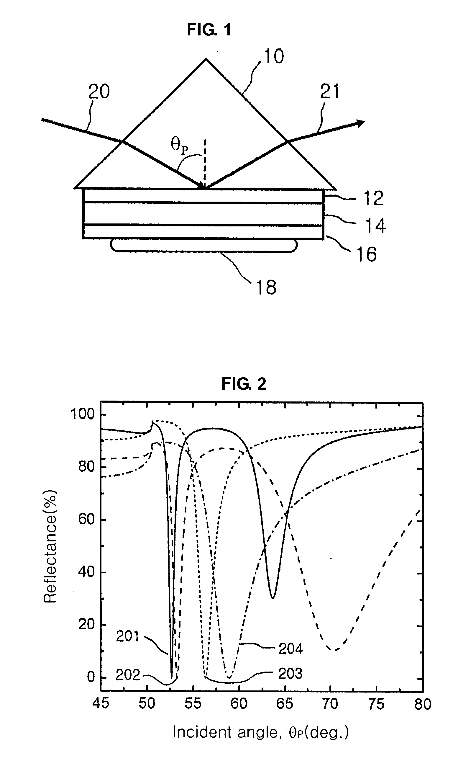
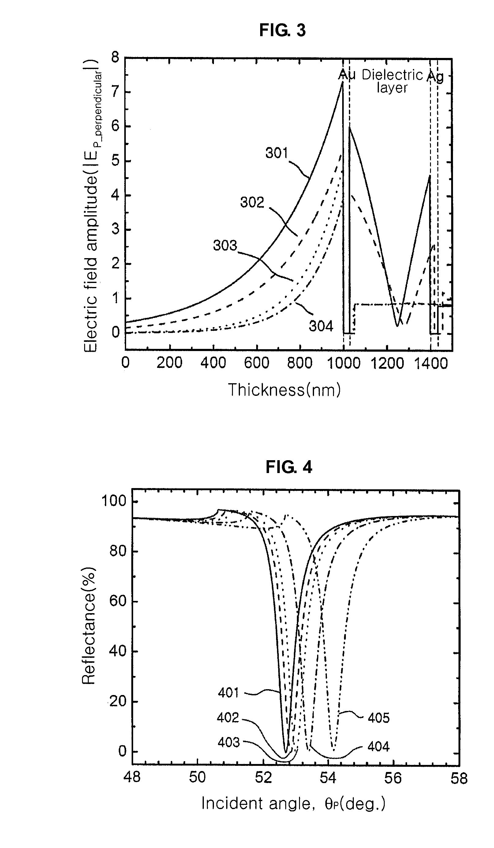
[0028]Exemplary embodiments now will be described more fully hereinafter with reference to the accompanying drawings, in which exemplary embodiments are shown. This disclosure may, however, be embodied in many different forms and should not be construed as limited to the exemplary embodiments set forth therein. Rather, these exemplary embodiments are provided so that this disclosure will be thorough and complete, and will fully convey the scope of this disclosure to those skilled in the art. In the description, details of well-known features and techniques may be omitted to avoid unnecessarily obscuring the presented embodiments.

[0029]The terminology used herein is for the purpose of describing particular embodiments only and is not intended to be limiting of this disclosure. As used herein, the singular forms “a”, “an” and “the” are intended to include the plural forms as well, unless the context clearly indicates otherwise. Furthermore, the use of the terms a, an, etc. does not de...


PUM

PropertyMeasurementUnit
wavelength regionaaaaaaaaaa
thicknessaaaaaaaaaa
thicknessaaaaaaaaaa

Abstract

Provided is a surface plasmon resonance sensor including: a part of delivering light by which a signal beam is incident to generate an evanescent field; and a part of exciting surface plasmon for exciting surface plasmons by the generated evanescent field and giving rise to a surface plasmon resonance, wherein a dielectric waveguide layer is inserted between metal layers of the part of exciting surface plasmon, and surface plasmon resonance properties are changed by an object to be analyzed.

Description

CROSS-REFERENCE TO RELATED APPLICATION[0001]This application claims priority to Republic of Korea Patent Application No. 10-2008-0119075, filed on Nov. 27, 2008, and all the benefits accruing therefrom under 35 U.S.C. §119(a), the contents of which in its entirety are herein incorporated by reference.BACKGROUND[0002]1. Field[0003]This disclosure relates to a biochemical sensor using the surface plasmon resonance phenomena that occur at an interface between a thin metal film and a dielectric, and more particularly, to a high-resolution surface plasmon resonance sensor and a system using the same, capable of narrowing the reflectivity curve due to the surface plasmon resonance, increasing the electric field intensity near the metal surface, thereby enhancing the responsivity to an environmental change, and extending a dynamic range of the sensor.[0004]2. Description of the Related Art[0005]Surface plasmons are charge density waves of free electrons which occur on a surface of a thin m...

Claims


Application Information

Patent Timeline
Patent Type & Authority Applications(United States)
IPC IPC(8): G01N21/55
CPCG01N21/553G01N21/00G01N21/25G01N21/552G01N33/50
Inventor LEE, KYEONG SEOKKIM, WON MOKLEE, TAEK SUNGCHEONG, BYUNG KI
Owner KOREA INST OF SCI & TECH
Why Eureka
Try Eureka