

Power storage device
a power storage device and power technology, applied in the direction of cell components, electrochemical generators, nickel accumulators, etc., can solve the problems of reducing outputs and adverse effects of power storage equipment performance, and achieve the effect of stable performan
- Summary
- Abstract
- Description
- Claims
- Application Information
AI Technical Summary
Benefits of technology
Problems solved by technology
Method used
Image

Examples
first embodiment
[0031]With reference to FIGS. 1 to 5, a power storage device according to a first embodiment will be described. The power storage device according to the present embodiment is a power storage module. The power storage module according to the present embodiment is a battery module including a plurality of fuel cells.
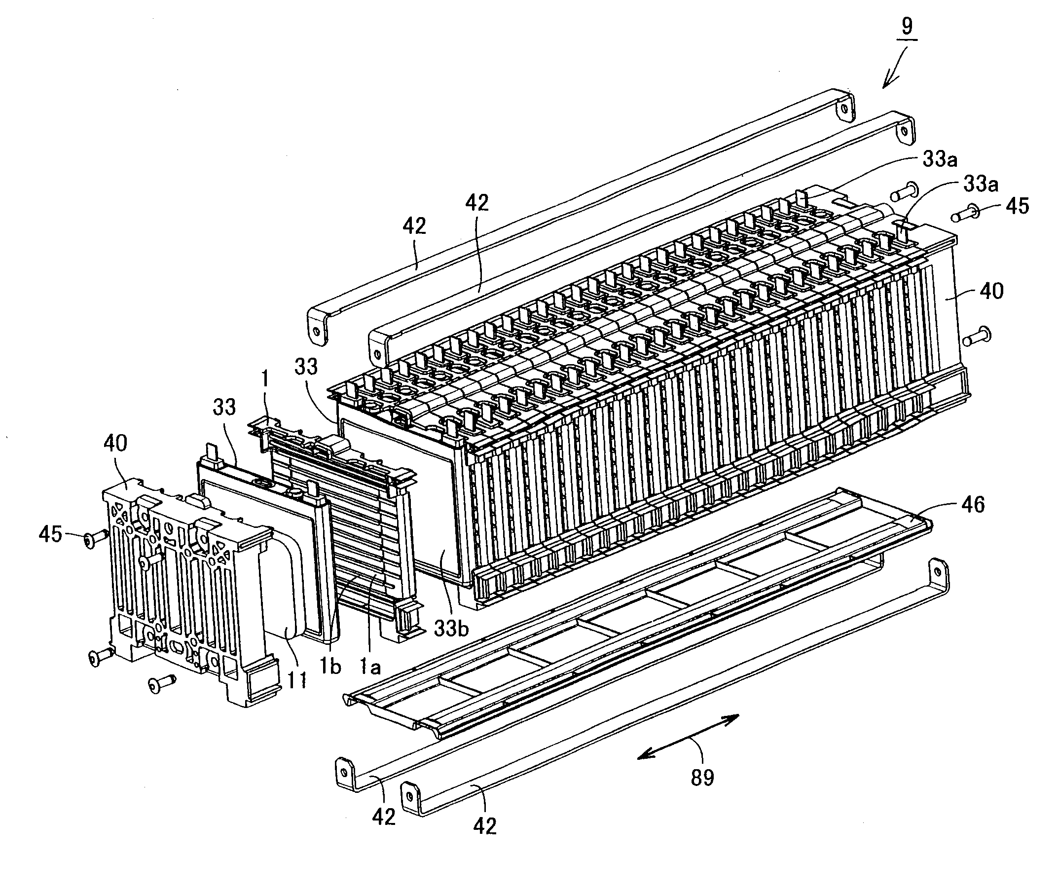
[0032]FIG. 1 is a schematic perspective view of the battery module according to the present embodiment. A battery module 9 according to the present embodiment is mounted on a hybrid vehicle powered by an internal combustion engine such as a gasoline engine and by a motor driven by a chargeable / dischargeable secondary battery.
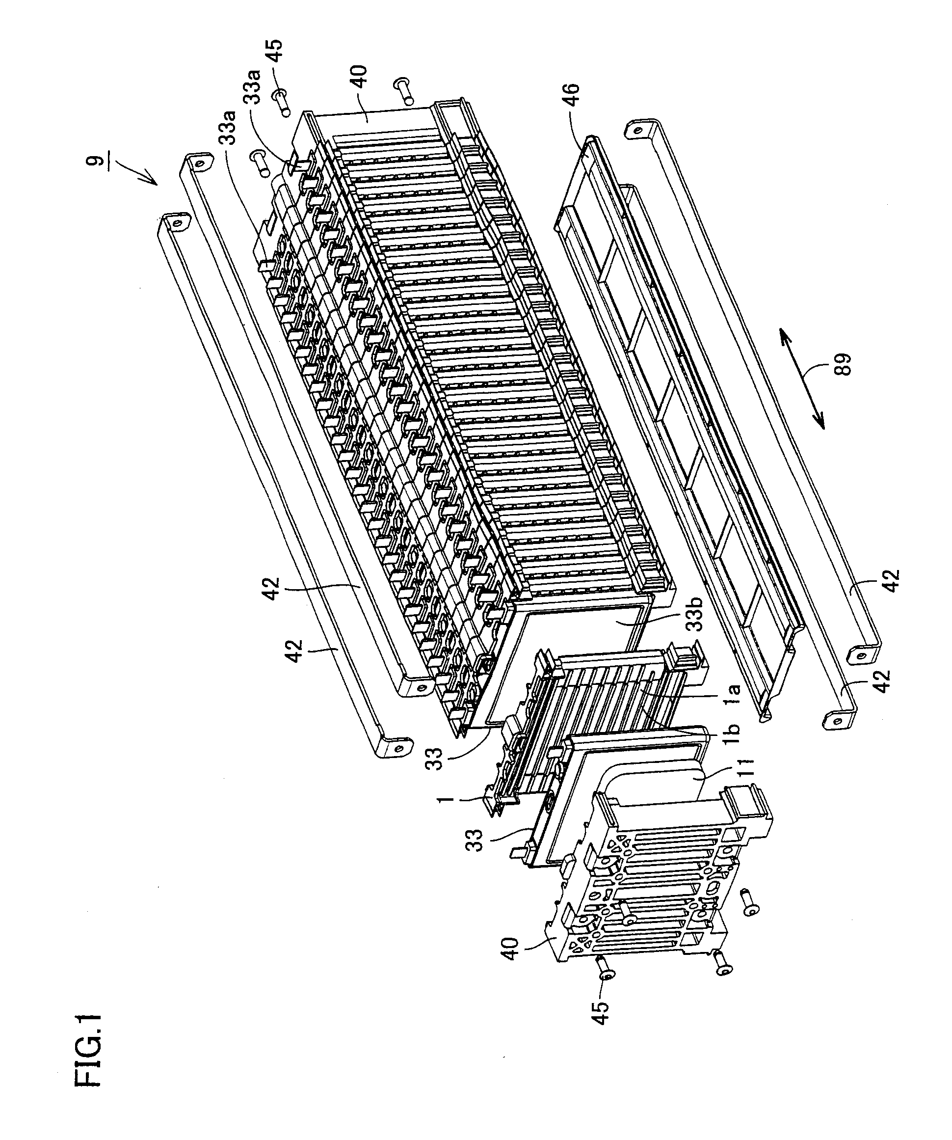
[0033]Battery module 9 includes fuel cells 33 serving as power storage cells. Battery module 9 includes a stacked body in which plurality of fuel cells 33 are stacked. Plurality of fuel cells 33 are stacked in the direction of thickness of fuel cells 33. An arrow 89 indicates the direction in which fuel cells 33 are stacked.
[0034]Fuel cells 33 accordi...
second embodiment
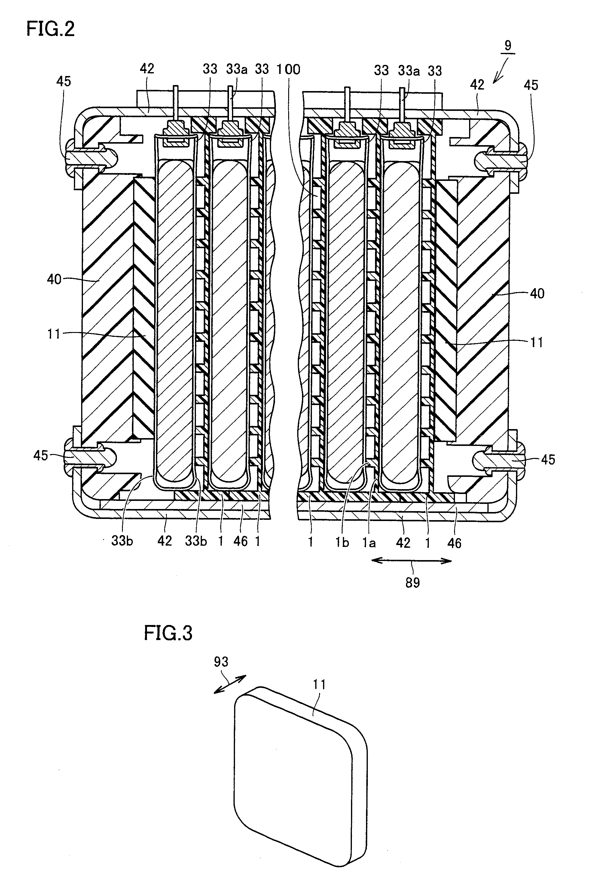
[0085]With reference to FIG. 3, a power storage device according to a second embodiment will now be described. The power storage device according to the present embodiment includes a battery module. Similarly to the first embodiment, the battery module includes a stacked body in which binding members and fuel cells are stacked, and interposed members are disposed within the stacked body. The battery module according to the present embodiment is different from that of the first embodiment in the structure of the interposed members.
[0086]The interposed members according to the present embodiment have a contour similar to that of interposed member 11 shown in FIG. 3. The interposed members according to the present embodiment include a porous member as a base. The porous member includes a member made of zeolite, activated carbon or the like. Zeolite includes synthetic zeolite, natural zeolite and artificial zeolite, for example. The interposed members according to the present embodiment...
third embodiment
[0093]With reference to FIGS. 6 and 7, a power storage device according to a third embodiment will now be described. The power storage device according to the present embodiment includes a battery module. The battery module according to the present embodiment is different from that of the first embodiment in the position at which interposed members are disposed.
[0094]FIG. 6 is a schematic sectional view of a first battery module according to the present embodiment. The first battery module according to the present embodiment includes interposed member 11. Interposed member 11 is disposed between two battery holders 1. Interposed member 11 is disposed in a space located between battery holders 1 in the stacked body of end plates 40, fuel cells 33 and battery holders 1. Interposed member 11 has front and back surfaces making contact with battery holders 1, respectively.
[0095]In this manner, in the first battery module according to the present embodiment, the interposed member is arran...
PUM
 Abstract
Description
Claims
Application Information