
Battery charging time optimization system

a battery and optimization technology, applied in the field of battery charging time optimization system, can solve the problem of optimizing the charge rate of batteries, and achieve the effect of reducing the requirements of the charging system and optimizing the charging rate of batteries

Active Publication Date: 2010-06-03
TESLA INC
View PDF0 Cites 41 Cited by
  • Summary
  • Abstract
  • Description
  • Claims
  • Application Information

AI Technical Summary

Benefits of technology

This approach ensures that the battery pack charges at an optimal rate, maximizing the use of available power and minimizing the impact of auxiliary loads, thus optimizing the charging time and efficiency.

Problems solved by technology

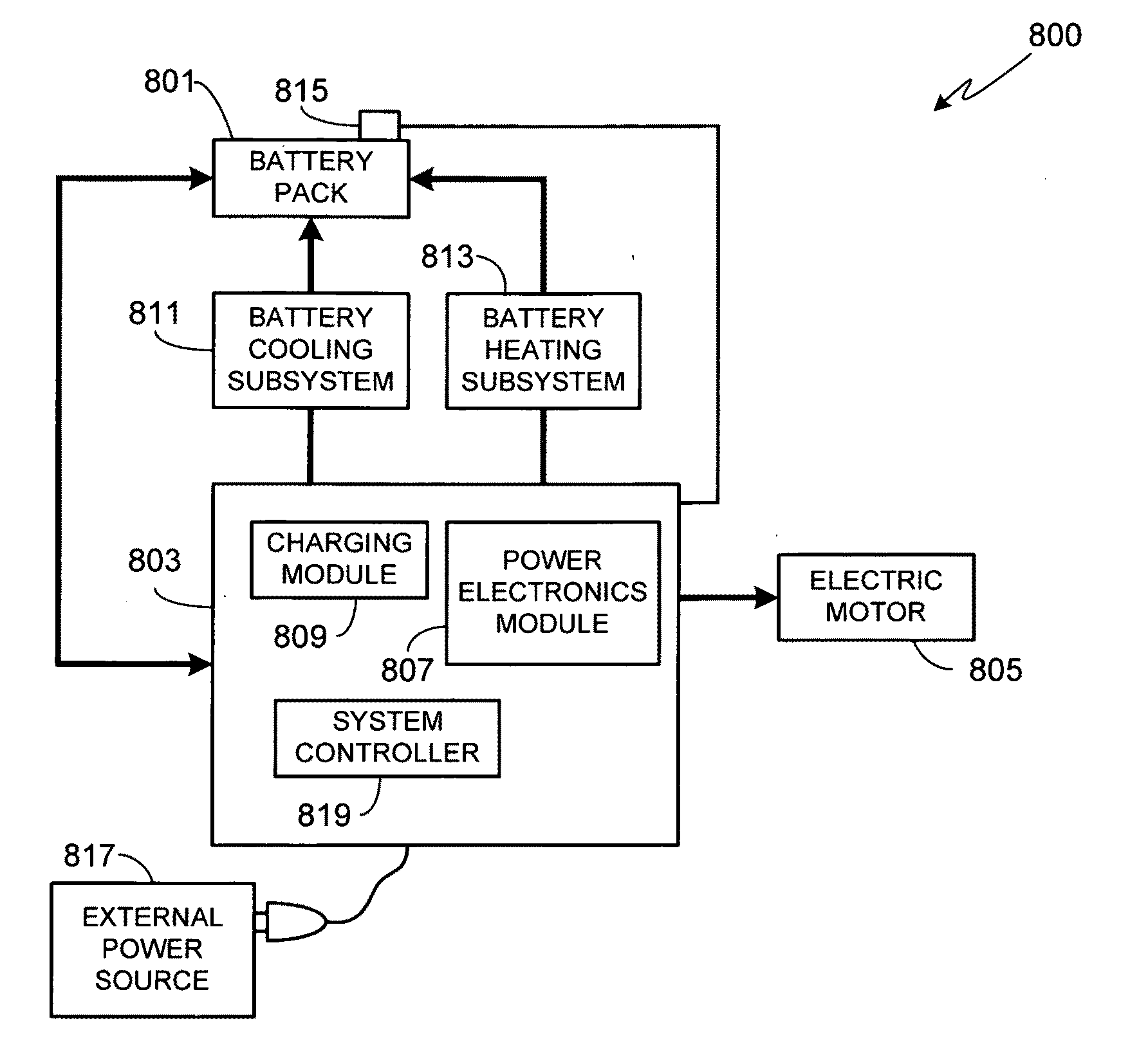
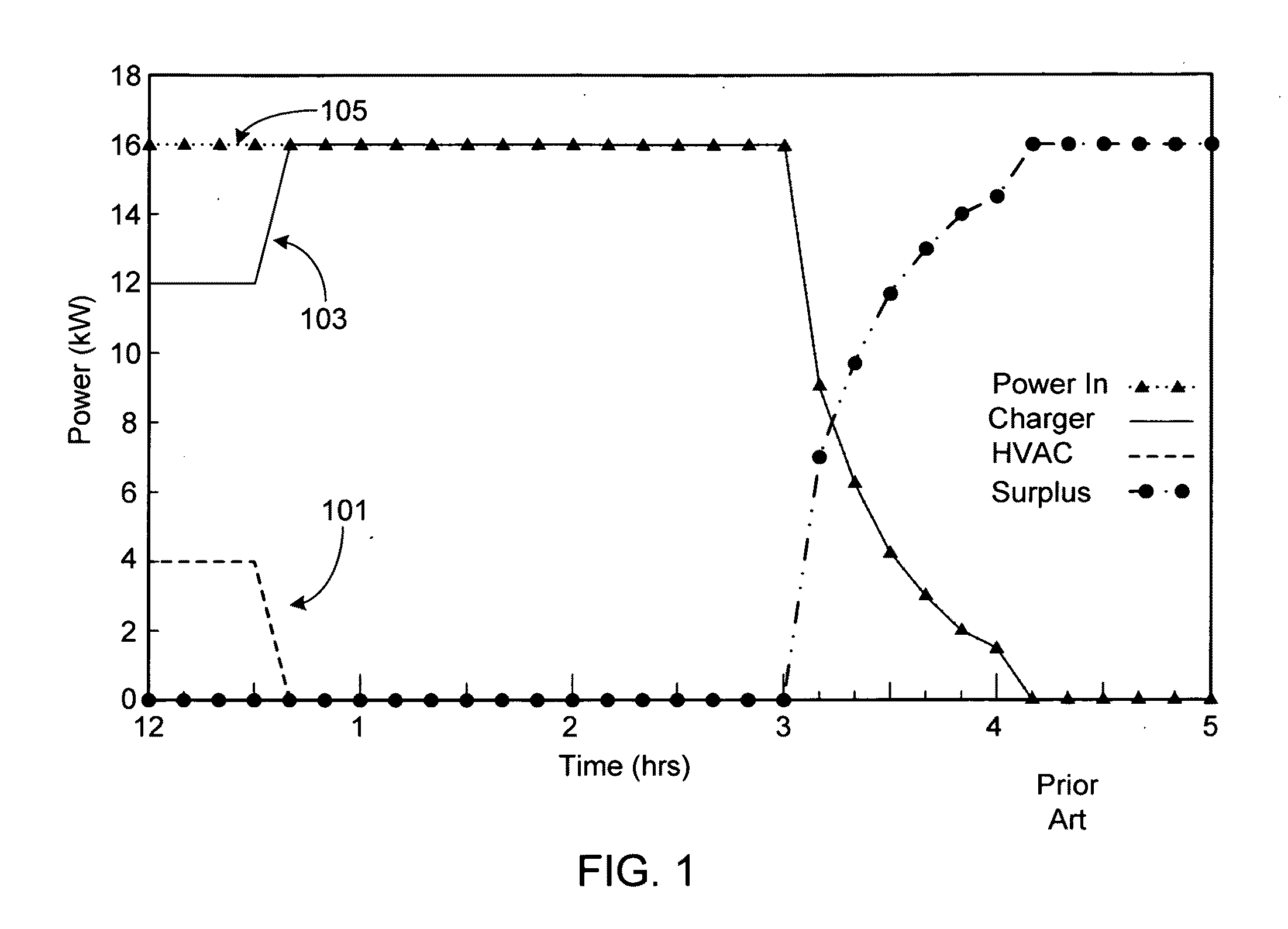
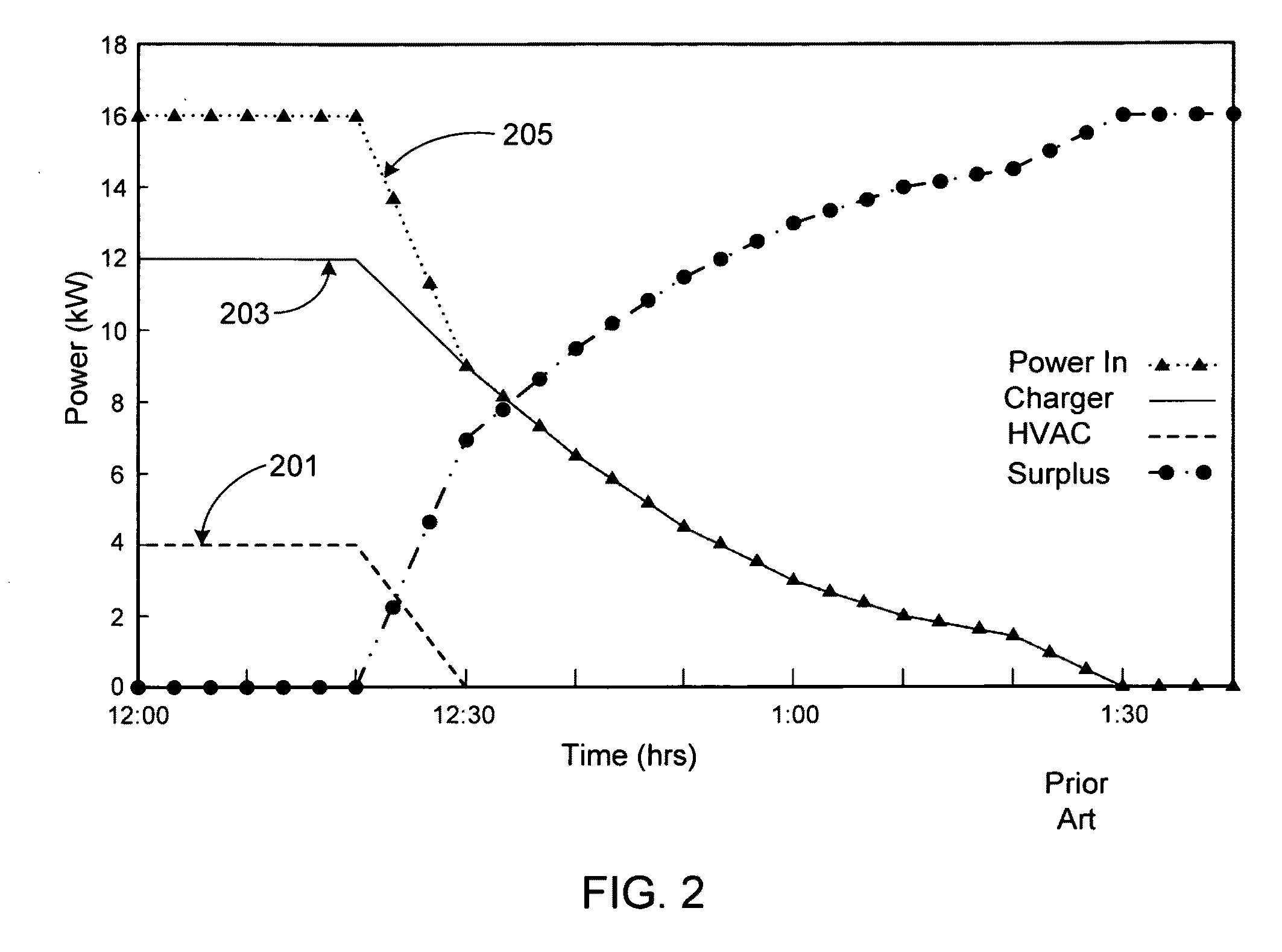
In this system, during charging the coupling of auxiliary systems (e.g., battery cooling systems) to the external power source are delayed so that the battery pack charge rate may be optimized, limited only by the available power.

Method used


Image

  • Battery charging time optimization system
  • Battery charging time optimization system
  • Battery charging time optimization system

Examples


Embodiment Construction

[0027]In the following text, the terms “battery”, “cell”, and “battery cell” may be used interchangeably and may refer to any of a variety of different rechargeable cell chemistries and configurations including, but not limited to, lithium ion (e.g., lithium iron phosphate, lithium cobalt oxide, other lithium metal oxides, etc.), lithium ion polymer, nickel metal hydride, nickel cadmium, nickel hydrogen, nickel zinc, silver zinc, or other battery type / configuration. The term “battery pack” as used herein refers to multiple individual batteries contained within a single piece or multi-piece housing, the individual batteries electrically interconnected to achieve the desired voltage and capacity for a particular application. The term “electric vehicle” as used herein refers to either an all electric vehicle, also referred to as an EV, a plug-in hybrid vehicle, also referred to as a PHEV, or a hybrid vehicle (HEV), a hybrid vehicle utilizing multiple propulsion sources one of which is ...


PUM


Abstract

A system for optimizing battery pack charging is provided. In this system, during charging the coupling of auxiliary systems (e.g., battery cooling systems) to the external power source are delayed so that the battery pack charge rate may be optimized, limited only by the available power. Once surplus power is available, for example as the requirements of the charging system decrease, the auxiliary system or systems may be coupled to the external power source without degrading the performance of the charging system.

Description

CROSS-REFERENCES TO RELATED APPLICATIONS[0001]This application is a continuation of U.S. patent application Ser. No. 12 / 612,770, filed Nov. 5, 2009, the disclosure of which is incorporated herein by reference for any and all purposes.FIELD OF THE INVENTION[0002]The present invention relates generally to batteries and, more particularly, to a method and apparatus for optimizing the charging time for a battery.BACKGROUND OF THE INVENTION[0003]Electric vehicles present a growing application for rechargeable batteries, and in particular for large battery packs. Such an application, however, presents a number of engineering challenges to the power system designer, primarily due to the need to balance the expectations of the consumer with the system requirements and the constraints placed on the system by the batteries within the battery pack. Consumer expectations include those associated with the vehicle as a whole, e.g., vehicle range, performance and reliability, and those that are sp...

Claims


Application Information

Patent Timeline
Patent Type & Authority Applications(United States)
IPC IPC(8): G06F19/00H02J7/04
CPCH02J7/0068Y02E70/40Y02B40/90H02J7/0091Y10S320/11B60L1/003B60L58/12Y02T10/70H02J7/007194Y02B40/00Y02E60/10Y02E60/13
Inventor KOHN, SCOTT IRA
Owner TESLA INC
Learn More