

Polymerized polymeric fluid storage and purification method and system
- Summary
- Abstract
- Description
- Claims
- Application Information
AI Technical Summary
Benefits of technology
Problems solved by technology
Method used
Image

Examples
example 1
Storage of a Gas in a Polymerized Polymeric Material
Arsine Stored in Nylon
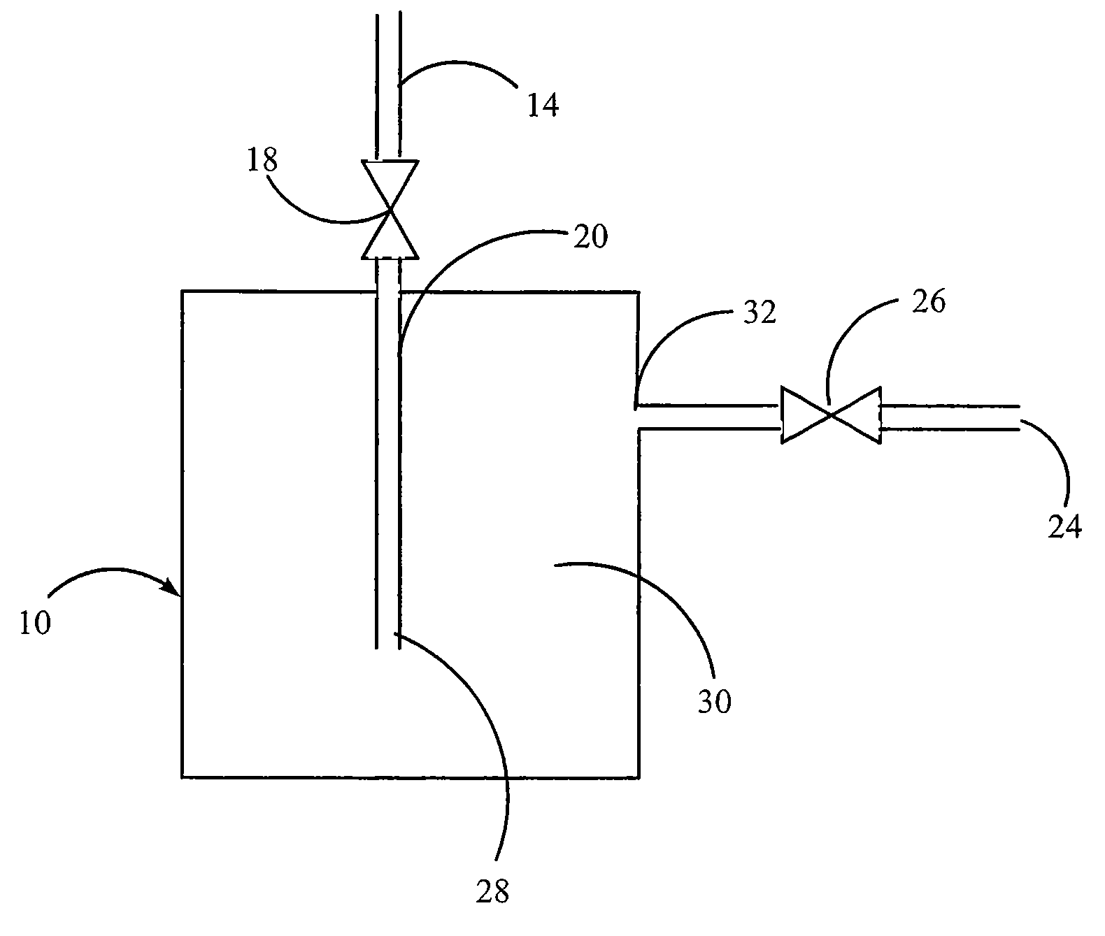
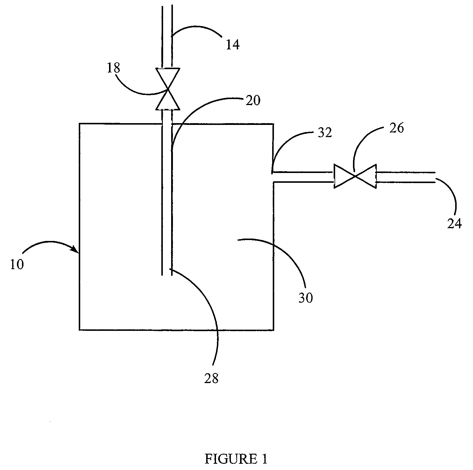
[0115]A vessel containing nylon is prepared as described above.
[0116]The source gas, AsH3 or a gas mixture containing AsH3, is then introduced into the vessel, at 5 psig, until the uptake of AsH3 is complete. The uptake can be determined gravimetrically, or by analytical methods. For example, the concentration or absolute amount of the AsH3 can be measured at the inlet of the vessel and the outlet of the canister. AsH3 will continue to be introduced until the inlet and outlet concentrations are equivalent, indicating the nylon is saturated and cannot accept any further AsH3 under the existing conditions. At this time, the source gas flow is stopped.
[0117]The nylon-charged vessel is then heated, a pressure differential is applied, or it is sparged with an inert gas, in order to deliver the stored AsH3. The delivered gas is analyzed for AsH3 content. This can be determined gravimetrically or analytically. The to...
example 2
Storage of a Gas in a Polymerized Polymeric Material
CO2 Stored in poly[1-(4-vinylbenzyl)-3-butyl Imidazolium Tetrafluoroborate] (PVBIT)
[0118]A vessel containing PVBIT is prepared as described above.
[0119]The source gas, CO2 or a gas mixture containing CO2, is then introduced into the vessel, at 5 psig, until the uptake of CO2 is complete. The uptake can be determined gravimetrically, or by analytical methods. For example, the concentration or absolute amount of the CO2 can be measured at the inlet of the vessel and the outlet of the canister. CO2 will continue to be introduced until the inlet and outlet concentrations are equivalent, indicating the PVBIT is saturated and cannot accept any further CO2 under the existing conditions. At this time, the source gas flow is stopped.
[0120]The PVBIT-charged vessel is then heated, a pressure differential is applied, or it is sparged with an inert gas, in order to deliver the stored CO2. The delivered gas is analyzed for CO2 content. This can ...
example 3
Storage and Stabilization and Purification of a Gas in a Polymerized Polymeric Material Using an Ionic Liquid Cosolvent
B2H6 Stored in poly[1-(4-vinylbenzyl)-3-butyl Imidazolium Tetrafluoroborate] (PVBIT) with 1-ethyl-3-methylimidazolium Tetrafluoroborate ([emim][BF4]) cosolvent
[0121]A vessel containing PVBIT is prepared as described above. A known amount of [emim][BF4] is added to the PVBIT-charged vessel and a vacuum bake procedure is conducted providing a PVBIT / [emim][BF4]-charged vessel.
[0122]The source gas, B2H6 or a gas mixture containing B2H6, is analyzed while by-passing the charged vessel, in order to determine the concentration of B2H6, impurities, and decomposition products. Once these concentrations in the source gas have been established, source gas is flowed into the PVBIT / [emim][BF4]-charged vessel at a pressure of 5 psig, until the uptake of B2H6 is complete. The uptake can be determined gravimetrically, or by analytical methods. For example, the concentration or abso...
PUM
| Property | Measurement | Unit |
|---|---|---|
| Time | aaaaa | aaaaa |
| Polymeric | aaaaa | aaaaa |
Abstract
Description
Claims
Application Information