
Cathode for Use in a Wet Capacitor

a technology of cathode and wet capacitor, which is applied in the direction of electrochemical machining apparatus, metal-working apparatus, metallic material coating process, etc., can solve the problems of low unit cell voltage of this type of capacitor and the inability to easily remove the coating

Inactive Publication Date: 2010-06-10
AVX CORP
View PDF100 Cites 64 Cited by
  • Summary
  • Abstract
  • Description
  • Claims
  • Application Information

AI Technical Summary

Benefits of technology

The present invention is about a type of capacitor that uses a wet electrolyte and a cathode that has a micro-roughened surface with elevated regions. The cathode is made by spark anodizing a metal substrate with an electrochemically-active material. The technical effect of this invention is to provide a capacitor with improved performance and stability.

Problems solved by technology

The unit cell voltage in this type of capacitor is generally low due to the inevitable decomposition of the electrolyte at high voltage.
However, under certain conditions, such as in the in the presence of aqueous electrolytes, the coatings can still become easily detached.

Method used


Image

  • Cathode for Use in a Wet Capacitor
  • Cathode for Use in a Wet Capacitor
  • Cathode for Use in a Wet Capacitor

Examples


example 1

[0045]The ability to form a tantalum electrode in accordance with the present invention was demonstrated. Initially, a tantalum foil (surface area of 1 square centimeter) was initially spot welded to a tantalum wire and degreased in an aqueous solution of an Alconox detergent (10 wt. % in deionized water) for 30 minutes in an ultrasonication bath. The tantalum foil was then rinsed with deionized water and dried at ambient temperature. Thereafter, the tantalum wire was spot welded to a stainless steel bar for holding the tantalum foil through an alligator clip. The tantalum foil was placed in an electrolyte solution containing 60 milliliters of 1M H3PO4 and 40 milliliters 1M H2SO4 in a 100-milliliter beaker. An electrochemical cell was created using the tantalum foil prepared above as the anode and a piece of platinum wire as the cathode. The connection to the cathode was attached to the stainless steel bar that was spot welded to the tantalum wire so that the distance between the pl...

example 2

[0046]A tantalum electrode was formed as described in Example 1, except that the electrolyte solution contained 50 milliliters 1M H3PO4 and 50 milliliters 1M H2SO4, and the distance between the platinum wire and tantalum foil was 0.5 centimeter. The duration of the experiment was 10 minutes during which the temperature was increased from 29° C. to 50° C. in the vicinity of the tantalum foil. SEM photographs of the resulting electrode are shown in FIGS. 2-5. The area of one elevated region was estimated using FIG. 4. More specifically, the area was calculated using the following equation for cylinders: Area=πr2+2πh, where r (base radius) was estimated as 2 micrometers and h (height) was estimated as 1.3 micrometers. From the above, it was determined that the elevated region had an approximate area of 28.9 μm2.


PUM

PropertyMeasurementUnit
heightaaaaaaaaaa
heightaaaaaaaaaa
thicknessaaaaaaaaaa

Abstract

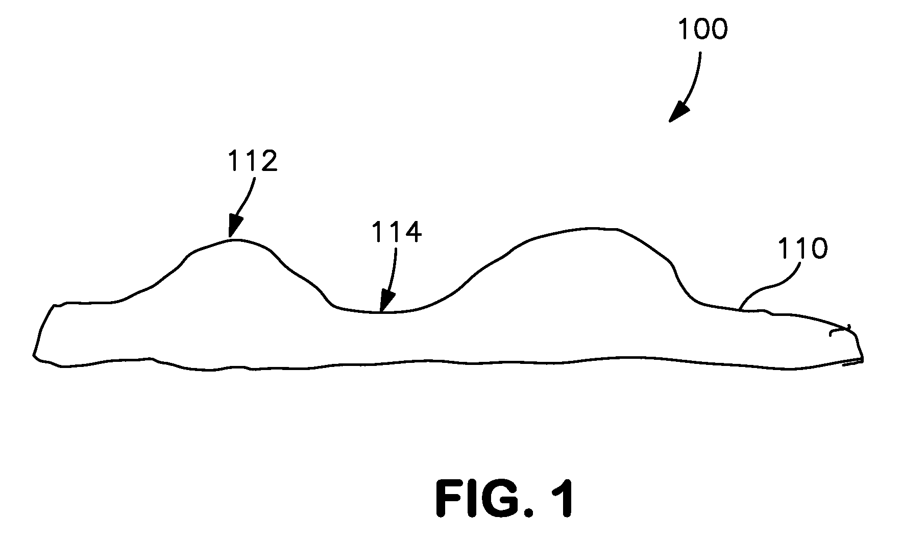
A cathode containing a metal substrate that possesses a micro-roughened surface imparted by spark anodization is provided. The surface is formed by contacting the substrate with an electrolytic solution and applying a voltage to form a dielectric sub-oxide layer. The voltage is raised to a sufficiently high level to initiate “sparking” at the surface of the substrate, which is believed to create high local surface temperatures sufficient to etch away the substrate. This results in the formation of a “micro-roughened” surface having a plurality elevated regions. These elevated regions can increase the effective surface area and thus allow for the formation of capacitors with increased cathode capacitance for a given size and / or capacitors with a reduced size for a given capacitance. The elevated regions may also exhibit excellent adhesion to additional electrochemically-active materials and provide enhanced stability in certain liquid electrolytes.

Description

BACKGROUND OF THE INVENTION[0001]Wet capacitors are increasingly being used in the design of circuits due to their volumetric efficiency, reliability, and process compatibility. Wet capacitors typically have a larger capacitance per unit volume than certain other types of capacitors, making them valuable in high-current, high power and low-frequency electrical circuits. One type of wet capacitor that has been developed is a wet electrolytic capacitor that includes a valve metal anode, a cathode, and a liquid electrolyte. The unit cell voltage in this type of capacitor is generally higher due to the formation of a dielectric metal oxide film over the anode surface. Wet electrolytic capacitors tend to offer a good combination of high capacitance with low leakage current. Another type of wet capacitor is a wet symmetric capacitor in which the anode and cathode are similar in terms of structure and composition. The unit cell voltage in this type of capacitor is generally low due to the ...

Claims


Application Information

Patent Timeline
Patent Type & Authority Applications(United States)
IPC IPC(8): H01G9/04C25D5/00
CPCH01G9/0032H01G9/055H01G9/0425H01G9/145H01G9/04H01G9/035
Inventor DREISSIG, DIRKRAWAL, BHARAT
Owner AVX CORP
Learn More