
Method of forming bilayer membrane by contact between amphipathic monolayers and apparatus therefor

a monolayer and amphipathic technology, applied in chemical analysis using titration, machine/engine, biomass after-treatment, etc., can solve the problems of difficult process for removal of intermediate liquid layer, large chamber of several cm in size, and inability to observe microscopically, etc., to achieve low reproducibility and long time

Active Publication Date: 2010-06-17
THE UNIV OF TOKYO
View PDF5 Cites 28 Cited by
  • Summary
  • Abstract
  • Description
  • Claims
  • Application Information

AI Technical Summary

Benefits of technology

The present invention provides a method and apparatus for forming a simple and accurate lipid bilayer membrane by contact of amphipathic monolayers. The conventional methods have drawbacks such as requiring large chambers and long drying times, and the conventional apparatuses have difficulty in reproducing the results. The present invention provides a method and apparatus that can overcome these drawbacks and form a bilayer membrane with ease and accuracy.

Problems solved by technology

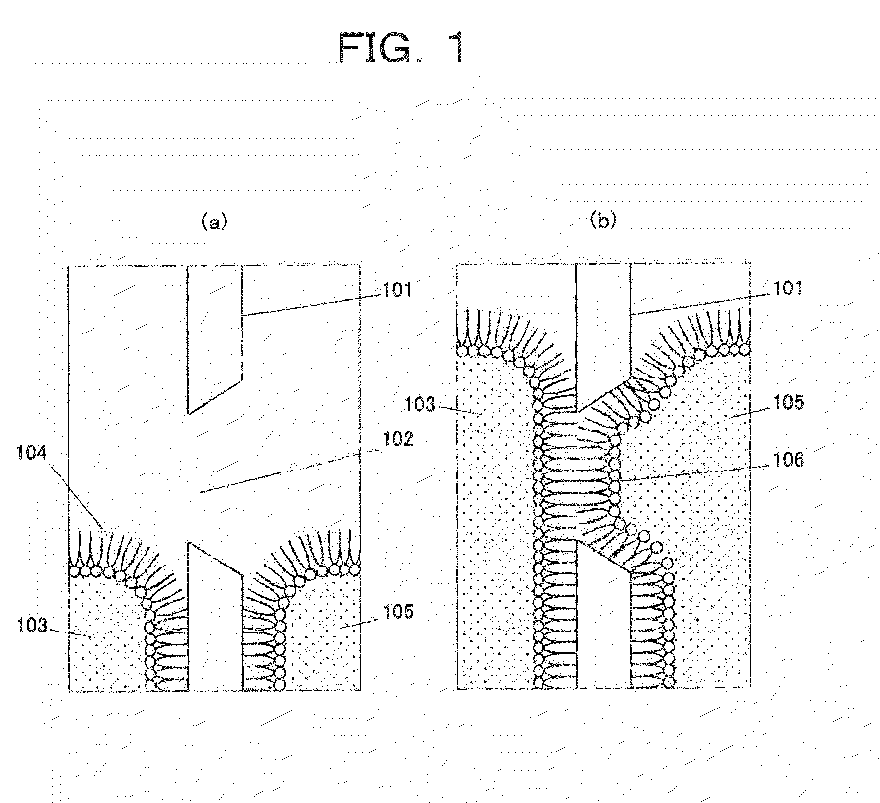
However, both methods, i.e. the brush coating method and the LB method described above, have such drawbacks that a large chamber of several cm in size is required, and that the microscopic observation is impossible because of the large dead volume.
The conventional method (1) mentioned above has also a drawback that the removal of the intermediate liquid layer requires a difficult process.
Moreover, the conventional method (2) mentioned above requires a great deal of time to complete all processes in that it requires the evaporation of solvent and the spontaneous thinning of the membrane both of which require a long time to be completed and suffer from low reproducibility.
As described above, the conventional methods have several problems in forming simple and accurate lipid bilayer membranes.

Method used


Image

  • Method of forming bilayer membrane by contact between amphipathic monolayers and apparatus therefor
  • Method of forming bilayer membrane by contact between amphipathic monolayers and apparatus therefor
  • Method of forming bilayer membrane by contact between amphipathic monolayers and apparatus therefor

Examples


first embodiment

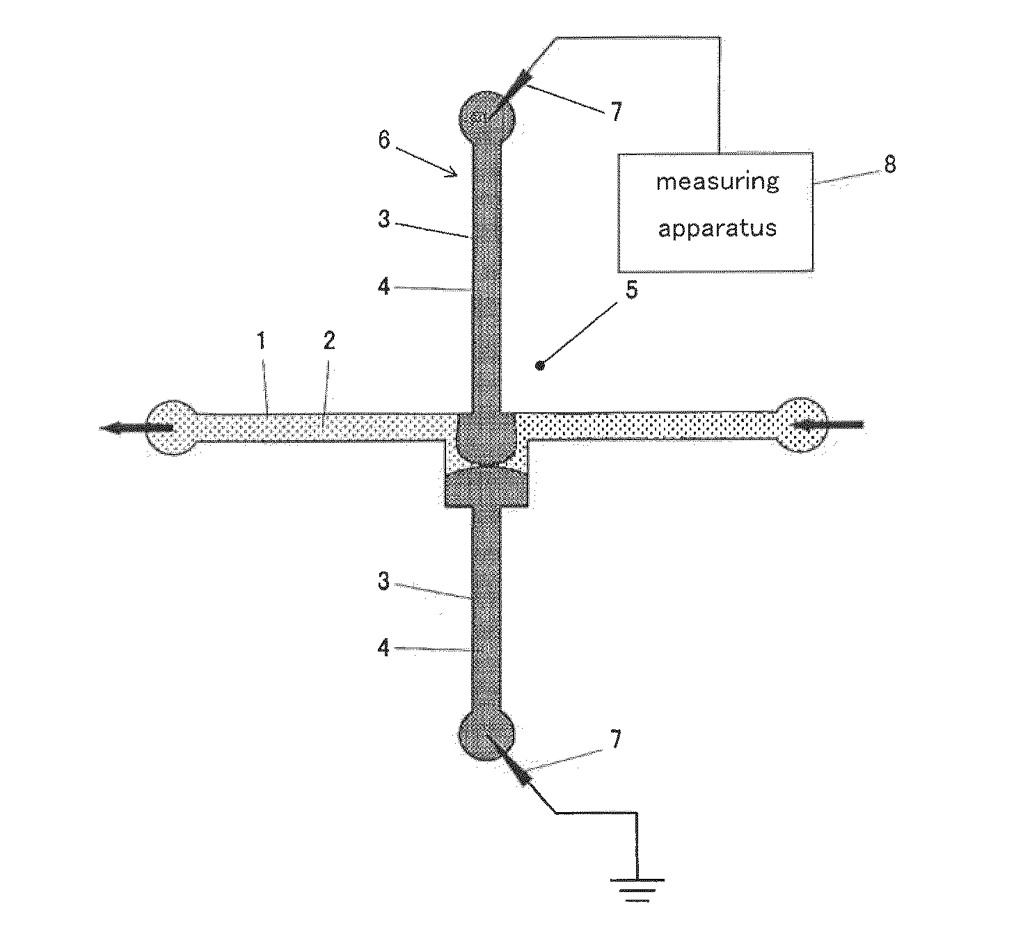
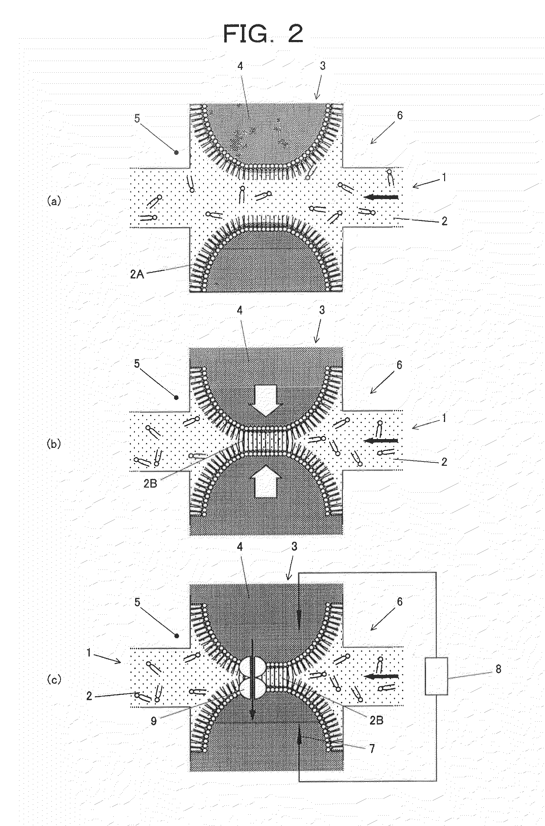
[0081]FIG. 2 is a view of a method of forming a bilayer by contact of monolayers using a substantially cross-shaped chamber in accordance with the present invention, and FIG. 2(a) is a view showing the state that the interfaces of aqueous solutions are not in contact with each other, while FIG. 2(b) is a view showing the state that the interfaces of aqueous solutions are in contact with each other.

[0082]Firstly, as shown in FIG. 2(a), an organic solvent 2 containing lipid molecules is introduced into a first microchannel 1 formed on a substrate 5. A second microchannel 3 is fabricated so as to cross orthogonally with the first microchannel 1, and a liquid 4 immiscible with the organic solvent 2 containing lipid molecules (for example, an aqueous solution) is introduced from the both ends of the second microchannel 3 toward the intersection of the first and the second microchannels. Syringe pumps (not shown in the view) are placed on the both ends of the second microchannel 3, and th...

second embodiment

[0098]FIG. 7 is a schematic plan view of an apparatus for forming lipid bilayer by the contact of monolayers including a plurality of compartments having a constriction portion in accordance with the present invention, and FIG. 8 is a schematic perspective view of a method of forming lipid bilayer using this apparatus.

[0099]Firstly, a chamber 12 separated by a constriction portion 13 is prepared on a substrate 11 opened in an upward direction as shown in FIG. 7(a) and FIG. 8(a). Next, the chamber 12 having the constriction portion 13 is filled with an organic solvent 14 containing lipid molecules as shown in FIG. 7(b) and FIG. 8(b). Next, liquid droplets 16 and 17 of an aqueous solution immiscible with the organic solvent 14 containing lipid molecules are added dropwise by a pipette 15 (see FIG. 8(c)) into each of a compartment of the chamber 12 separated by the constriction portion 13 as shown in FIG. 7(c) and FIG. 8(c). Then, in this state, lipid monolayers 18 are formed on the in...

third embodiment

[0110]FIG. 12 is a schematic plan view of an apparatus for forming two lipid bilayers including a chamber separated into three in lateral sequences by two constriction portions in accordance with the present invention.

[0111]In accordance with this embodiment, a chamber 42 with a lateral series of two constriction portions 43 and 44 is prepared, and an organic solvent 45 containing lipid molecules is introduced into the chamber 42. By introducing three liquid droplets 46, 47, and 48 thereto, a first lipid bilayer 49 is formed on the contact surface of the liquid droplets 46 and 47, and a second lipid bilayer 50 is formed on the contact surface of the liquid droplets 47 and 48.


PUM

PropertyMeasurementUnit
sizeaaaaaaaaaa
voltageaaaaaaaaaa
depthaaaaaaaaaa

Abstract

The present invention provides a simple and an accurate method of forming a bilayer membrane by the contact of amphipathic monolayers and an apparatus therefor. The method is characterized in that the organic solvent (2) containing lipid molecules is introduced into a first microchannel (1) formed on a substrate (5). A liquid (4) immiscible with the organic solvent (2) containing lipid molecules is introduced into a second microchannel (3), which crosses the first microchannel (1) from both sides to form an intersection, from both ends of the second microchannel (3) toward the intersection. Amphipathic monolayers (2A) opposing each other are formed at the interfaces between the liquid (4) and the organic solvent (2), and finally a lipid bilayer membrane (2B) is obtained by bringing the amphipathic monolayers (2A) into contact and fusing, by the contact of the interfaces of the liquid (4) introduced from the both ends of the second microchannel (3) with the control of the pressure of the liquid (4) using syringe pumps.

Description

TECHNICAL FIELD[0001]The present invention relates to a method and an apparatus of forming a bilayer membrane for analyzing membrane proteins used in the field of biotechnology, biochips, analysis of membrane proteins, drug screening assays, and biosensors.BACKGROUND ART[0002]Membrane proteins, which are present in cell membranes, play an important role in immune reactions and material transports / releases to inside and outside of the cells. Therefore, for the development of the method of therapy and drug discovery in the next generation, it is an important subject to clarify each functions and characteristics of various kinds of membrane proteins.[0003]Typical conventional art for fabricating planar lipid membranes used for analyzing membrane proteins such as an ion channel is a planar membrane method, i.e., brush coating method or LB method (Langmuir-Blodgett method). In both of the methods, a lipid bilayer is formed in a tiny aperture of several hundred microns in size pierced on ...

Claims


Application Information

Patent Timeline
Patent Type & Authority Applications(United States)
IPC IPC(8): B29C65/70B32B37/02B32B38/00B01J19/00B01L99/00
CPCB01L3/502769G01N33/92G01N33/68
Inventor TAKEUCHI, SHOJISUZUKI, HIROAKIFUNAKOSHI, KEI
Owner THE UNIV OF TOKYO
Learn More