Eureka AIR delivers breakthrough ideas for toughest innovation challenges, trusted by R&D personnel around the world.

Electrophoretic media and processes for the production thereof

a technology processes, applied in the field can solve the problems of inadequate preventing their widespread use, and reducing the service life of encapsulated electrophoretic displays, both single and dual particle types

Inactive Publication Date: 2010-06-17
E INK CORPORATION
View PDF102 Cites 119 Cited by
  • Summary
  • Abstract
  • Description
  • Claims
  • Application Information

AI Technical Summary

Benefits of technology

This patent describes an electrophoretic medium that uses a hydrocarbon or halocarbon as a suspending fluid. The medium includes electrically charged particles suspended in the fluid. The particles have a polymeric shell made up of repeating units derived from at least one monomer that is incompatible with the suspending fluid. This results in a two-particle system where one particle has a different optical characteristic than the other particles. The invention also provides an electrophoretic particle that has a polymeric shell made up of repeating units derived from at least one monomer that is compatible with the suspending fluid. The use of this incompatible monomer results in a more stable and efficient electrophoretic medium.

Problems solved by technology

Nevertheless, problems with the long-term image quality of these displays have prevented their widespread usage.
For example, particles that make up electrophoretic displays tend to settle, resulting in inadequate service-life for these displays.
However, the service life of encapsulated electrophoretic displays, of both the single and dual particle types, is still lower than is altogether desirable.
In this regard, opposite charge dual particle electrophoretic displays pose a particularly difficult problem, since inherently oppositely charged particles in close proximity to one another will be electrostatically attracted to each other and will display a strong tendency to form stable aggregates.
Experimentally, it has been found that if one attempts to produce a black / white encapsulated display of this type using untreated commercially available titania and carbon black pigments, the display either does not switch at all or has a service life so short as to be undesirable for commercial purposes.
Later, it was found that simple coating of the electrophoretic particles with the modifying material was not entirely satisfactory since a change in operating conditions might cause part or all of the modifying material to leave the surface of the particles, thereby causing undesirable changes in the electrophoretic properties of the particles; the modifying material might possibly deposit on other surfaces within the electrophoretic display, which could give rise to further problems.
Furthermore, a polymer with only a few sites capable of reacting with the particle material has difficulty in reacting with the solid interface at the particle surface; this can be due to polymer chain conformation in solution, steric congestion at the particle surface, or slow reactions between the polymer and the surface.
Often, these problems restrict such reactions to short polymer chains, and such short chains typically only have a small effect on particle stability in electrophoretic media.
However, electrophoretic displays do not have unlimited image stability.
Refreshing the display consumes power, and thus diminishes the utility of the display.
In addition, in certain applications (active matrix driven displays in particular) it is difficult or impossible to accomplish the refreshing of a single pixel without a blanking pulse (i.e., a pulse which drives the pixel to one of its extreme optical states before it is driven to the final desired optical state cf. the aforementioned 2003 / 0137521.
However, its use as a solvent in processes for preparing polymer-coated electrophoretic pigment particles is markedly inconvenient.
These washing, centrifuging and drying steps are labor intensive and costly.
Further expense is incurred by the need to re-disperse the dried pigment in the final suspending fluid.
Furthermore, because of the presence of the toluene and THF, the washing, centrifuging and drying steps tend to be hazardous and commercial scale production of the polymer-coated pigment requires the use of explosion-proof ovens, mixers and centrifuges, and explosion-proof electrical control panels, which substantially increases the costs of the production equipment.
Also, operator exposure to vapors during processing can be significant despite the use of protective devices or exposure prevention methods.
Finally, the drying step may be detrimental to the performance of the pigment in the final electrophoretic medium.
Fabrication processes, however, can result in significant cost.
The voltage biases can cause errors in the optical states of pixels, as well as degrade the electro-optic medium.
This technique, however, can cause a large gate-pixel capacitance.
A large gate-pixel capacitance is undesirable because it can create a need for a large compensation in one of the select line voltage levels.
Moreover, existing addressing structures can produce unintended bias voltages, for example, due to pixel-to-pixel variations in gate-pixel capacitance.
Such voltages can produce a detrimental effect on certain electro-optic media, particularly when present for extended periods of time.
The foregoing problems render designing a bistable electro-optic display using a electro-optic medium without a voltage threshold a difficult task.
Even if these coupled voltage spikes are, over the long term, constrained to be DC balanced, continuous application of these voltage spikes may result in changes in the optical state of the pixels.
In the prior art, essentially the only practicable way to minimize or eliminate the effects of these voltage spikes is to increase the size of the pixel storage capacitor, which increases the power consumption of the display considerably.
In addition, the large size of the storage capacitor limits the maximum achievable resolution, and may result in a decrease in panel yield by increasing the area of metal-metal overlap.

Method used


Image

  • Electrophoretic media and processes for the production thereof
  • Electrophoretic media and processes for the production thereof
  • Electrophoretic media and processes for the production thereof

Examples


Embodiment Construction

[0086]As already indicated, the present invention relates to electrophoretic media using particles having polymeric shells, electrophoretic particles for use in such media, electrophoretic displays containing such media or similar electro-optic media, and processes for the preparation of the aforementioned polymeric shells. Accordingly, before describing the various aspects of the present invention in detail, it is believed desirable to provide a general introduction regarding electrophoretic particles, processes for forming polymer shells thereon, the electrophoretic media and display incorporating such particles.

[0087]General Introduction

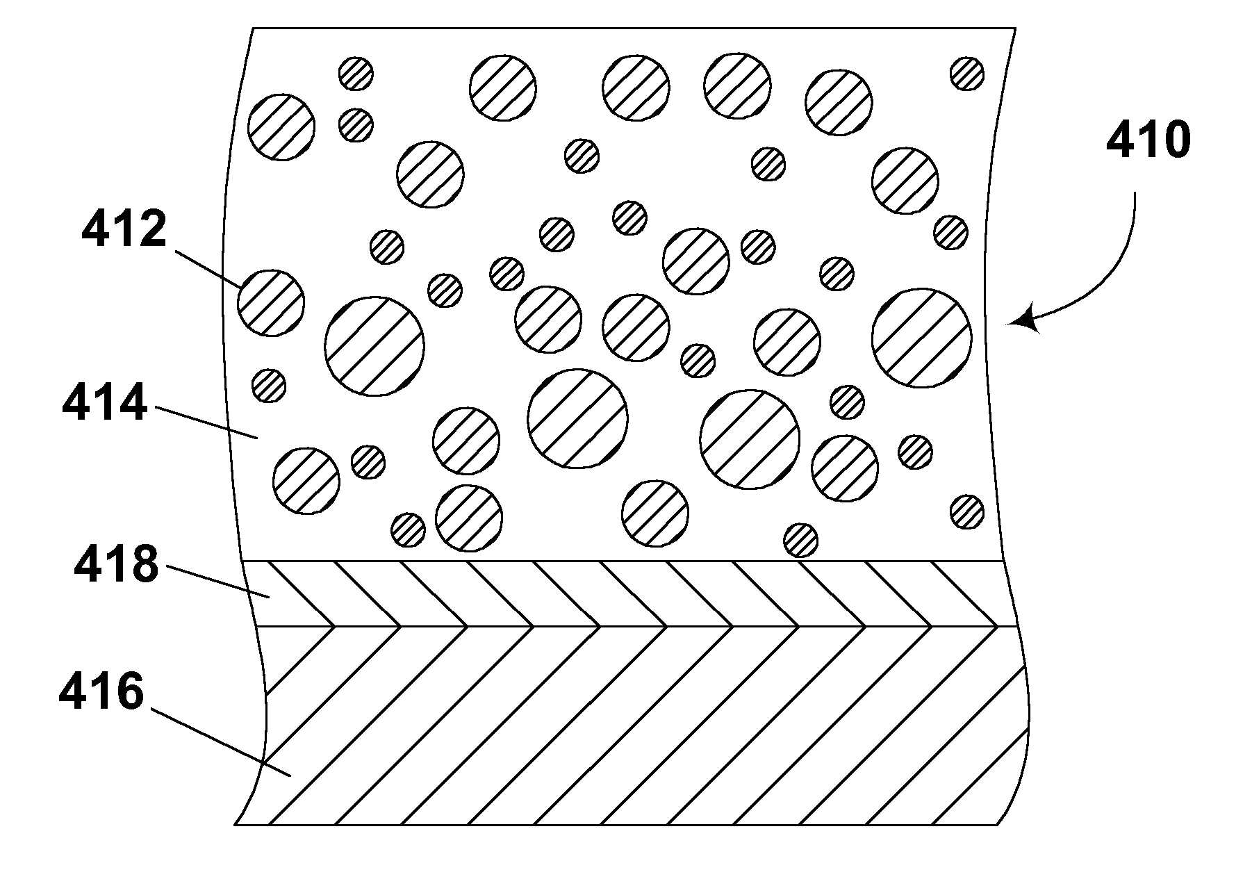
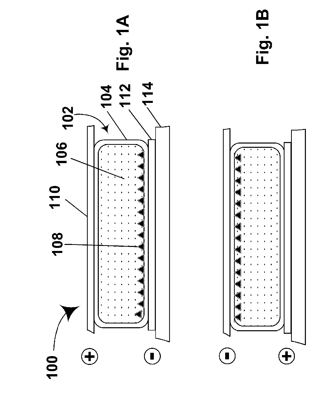
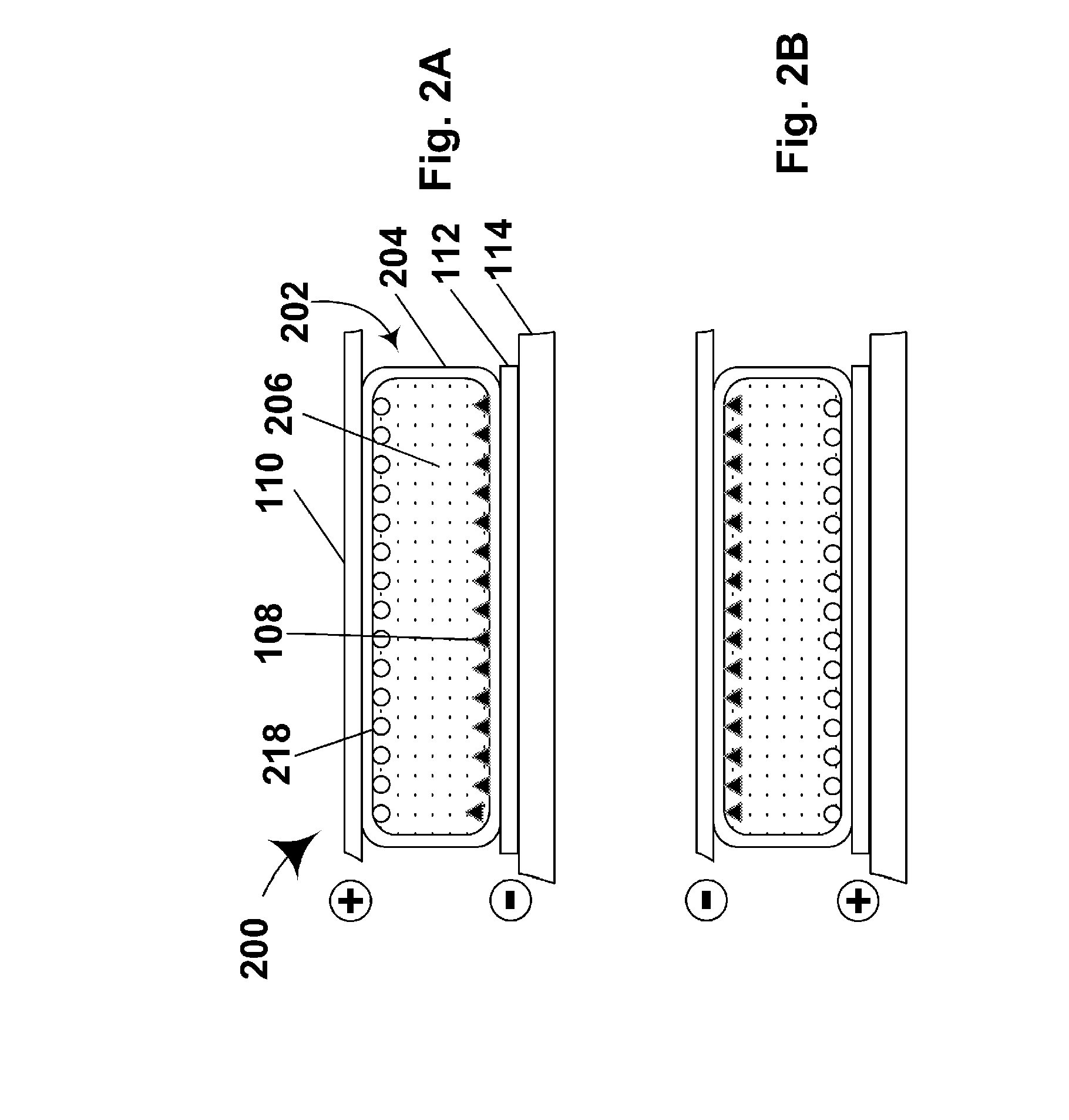
[0088]The electrophoretic medium of the present invention may be of any of the types described in the aforementioned E Ink and MIT patents and applications, and preferred embodiments of such media will now be described with reference to FIGS. 1 to 4 of the accompanying drawings.

[0089]The first electrophoretic display (generally designed 100) of th...


PUM

PropertyMeasurementUnit
electrophoreticaaaaaaaaaa
voltage thresholdaaaaaaaaaa
optical propertyaaaaaaaaaa

Abstract

A first electrophoretic medium comprises an electrically charged particle suspended in a suspending fluid, the particle having a polymeric shell having repeating units derived from at least one monomer the homopolymer of which is incompatible with the suspending fluid. A second, similar electrophoretic medium comprises a suspending fluid, and first and second types of electrically charged particle suspended in the suspending fluid, the two types of particle having differing optical characteristics but both having polymeric shells. The polymeric shells are arranged such that homoaggregation of the two types of particles is thermodynamically favored over heteroaggregation.

Description

REFERENCE TO RELATED APPLICATIONS[0001]This application is a divisional of copending application Ser. No. 12 / 434,218, filed May 1, 2009 (Publication No. 2009 / 0206499), which is itself a divisional of application Ser. No. 11 / 743,226 filed May 2, 2007 (Publication No. 2007 / 0200795, now U.S. Pat. No. 7,532,388, issued May 12, 2009), which is itself a divisional of application Ser. No. 10 / 711,829, filed Oct. 7, 2004 (Publication No. 2005 / 0168799, now U.S. Pat. No. 7,230,750, issued Jun. 12, 2007), which is itself a continuation-in-part of copending application Ser. No. 10 / 708,130, filed Feb. 9, 2004 (now U.S. Pat. No. 7,002,728), which itself is a continuation-in-part of copending application Ser. No. 10 / 063,803 filed May 15, 2002 (now U.S. Pat. No. 6,822,782), which claims benefit of Application Ser. No. 60 / 291,081, filed May 15, 2001.[0002]The aforementioned application Ser. No. 10 / 711,829 also claims benefit of the following provisional applications: (a) Application Ser. No. 60 / 481,4...

Claims


Application Information

Patent Timeline
Patent Type & Authority Applications(United States)
IPC IPC(8): B01J13/02C08F130/08C08F120/18C08G79/00G02F1/167
CPCG02F1/167G02F2202/022G02F2001/1678
Inventor BALKO, SUZANNEGOENAGA, ALBERTOVALIANATOS, PETER J.HONEYMAN, CHARLES H.GATES, ELIZABETH M.KING, MATTHEW A.
Owner E INK CORPORATION
Why Eureka
Eureka Blog
Learn More