Nanofiber spinning method and device

Active Publication Date: 2010-06-17
PANASONIC CORP
View PDF3 Cites 35 Cited by
  • Summary
  • Abstract
  • Description
  • Claims
  • Application Information

AI Technical Summary

Benefits of technology

[0036]According to the nanofiber spinning method and device of the present invention, nanofibers made of polymeric substances are produced by an electrospinning method, and the produced nanofibers are attracted to the collecting electrode unit while being rotated, an

Problems solved by technology

However, since, in the conventional electrospinning method, only a small amount of nanofibers can be produced from the tip of a single nozzle, high productivity cannot be obtained.
However, it is difficult for thus produced nanofiber web to achieve physical properties of 10 MPa or more, which imposes a limitation in a

Method used


Image

  • Nanofiber spinning method and device
  • Nanofiber spinning method and device
  • Nanofiber spinning method and device

Examples


first embodiment

[0090]Firstly, first embodiment of a nanofiber spinning device according to the present invention will be described with reference to FIG. 1 to FIG. 4.

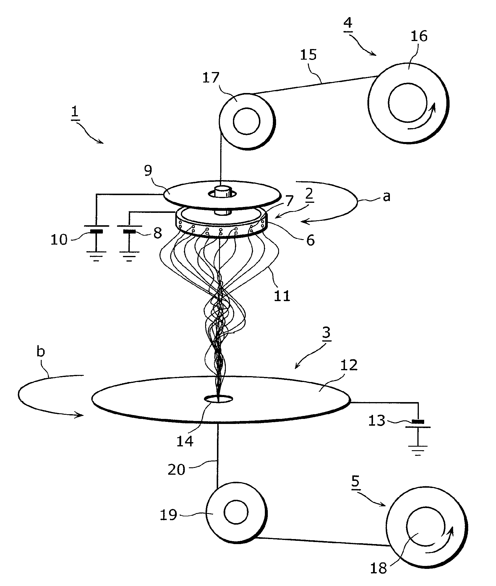
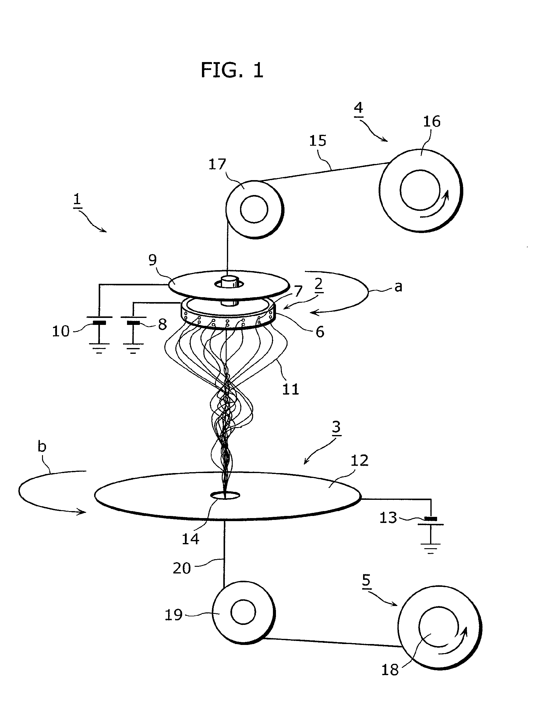
[0091]FIG. 1 is a perspective view of an overall schematic structure of a nanofiber spinning device 1 according to the first embodiment of the present invention.

[0092]The nanofiber spinning device 1 is a device which produces nanofibers and rotates the produced nanofibers for spinning. As shown in FIG. 1, the nanofiber spinning device 1 includes a nanofiber producing unit 2, a collecting electrode unit 3, a core yarn feeding unit 4, and a collecting unit 5.

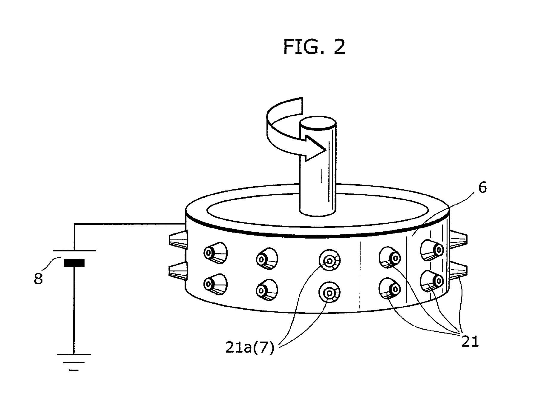
[0093]The nanofiber producing unit 2 includes a cylindrical container 6, a first high voltage generating unit 8, a reflecting electrode 9, and a second high voltage generating unit 10.

[0094]The cylindrical container 6 is a rotary container which is pivotally supported about its vertical central axis. The cylindrical container 6 has an outer circumferential surface formed with small ...

second embodiment

[0135]Next, second embodiment of a nanofiber spinning device 1 according to the present invention is described with reference to FIG. 6 and FIG. 7. Note that in the following descriptions of embodiments, identical reference numerals are assigned to elements identical to those described in the previous embodiment, and descriptions thereof are omitted. Only differences from the previous embodiment are mainly described.

[0136]FIG. 6 is a longitudinal elevation view of an overall schematic structure of a nanofiber spinning device 1 according to second embodiment of the present invention.

[0137]In the first embodiment, an example has been described where a core yarn feeding unit 4, a nanofiber generating unit 2, a collecting electrode unit 3, and a collecting unit 5 are provided in a vertical direction from the top to the bottom in the mentioned order, a cylindrical container 6 and a collecting electrode 12 are rotated about the vertical central axis, and produced nanofibers 11 are directe...

third embodiment

[0152]Next, third embodiment of a nanofiber spinning device according to the present invention will be described with reference to FIG. 8 to FIG. 12.

[0153]FIG. 8 is a perspective view of an overall schematic structure of a nanofiber spinning device 1 according to the third embodiment of the present invention.

[0154]In the first embodiment described above, as an example of the structure of the collecting electrode unit 3, the collecting electrode 12 is rotated; however, in the present embodiment, as shown in FIG. 8, a rotating electric field generating unit 45 is provided for generating, around the through-hole 14, a rotating electric field.

[0155]FIG. 9 is a perspective view of a schematic structure of a collecting electrode unit 3 according to the third embodiment of the present invention.

[0156]FIG. 10 is a phase diagram showing voltages applied to each divided electrode in the collecting electrode unit 3.

[0157]As shown in FIG. 9, the rotating electric field generating unit 45 circul...


PUM

PropertyMeasurementUnit
Electric potential / voltageaaaaaaaaaa
Strengthaaaaaaaaaa
Electric fieldaaaaaaaaaa

Abstract

Provided is a nanofiber spinning method and device for producing a high strength and uniform yarn made of nanofibers with high productivity and at a low cost.
The device includes: a nanofiber producing unit (2) which produces nanofibers (11) by extruding polymer solution, prepared by dissolving polymeric substances in a solvent, through small holes (7) and charging the polymer solution, and by allowing the polymer solution to be stretched by an electrostatic explosion, and which allows the nanofibers to travel in a single direction; a collecting electrode unit (3) to which an electric potential different from that of the charged polymer solution is applied, and which attracts the produced nanofibers (11) while simultaneously rotating and twisting the nanofibers, and gathers them for forming a yarn (20) made of the nanofibers (11); and a collecting unit (5) which collects the yarn (20) passed through the center of the collecting electrode unit (3).

Description

TECHNICAL FIELD[0001]The present invention relates to a nanofiber spinning method and device for producing nanofibers made of polymeric substances and forming the produced nanofibers into yarn.BACKGROUND ART[0002]Conventionally, electrospinning (also referred to as electric charge induced spinning) is known as a method for producing nanofibers made of polymeric substances and having a diameter in submicron order.[0003]In the conventional electrospinning method, a polymer solution is supplied to a needle nozzle to which a high voltage is applied, so that the polymer solution extruded as filaments through the needle nozzle is electrically charged. As a solvent of the polymer solution which is electrically charged evaporates, a distance between these electric charges decreases and Coulomb force acting thereon increases. When the increased Coulomb force exceeds the surface tension of the filamentous polymer solution, the filamentous polymer solution undergoes a phenomenon in which the f...

Claims


Application Information

Patent Timeline
IPC IPC(8): D01D5/098B29C47/00D01D5/04D01G1/00D02G3/02D04H1/728
CPCD01D5/0069D01D5/0076D02J1/22D01D5/18D02G3/36D01D5/0092B82Y40/00D01D5/00D02G3/02
Inventor SMIDA, HIROTOKUROKAWA, TAKAHIROISHIKAWA, KAZUNORITAKAHASHI, MITSURHIROTAKEZAWA, MIKIOTOMINAGA, YOSHIAKI
Owner PANASONIC CORP
Why Eureka
Try Eureka