Optical receiver, optical line terminal and method of recovering received signals

a receiver and optical line technology, applied in the field of optical receivers, can solve the problems of predetermined transmission penalty, optical power penalty due to a bit intensity noise created, optical power penalty,

Inactive Publication Date: 2010-06-17
ELECTRONICS & TELECOMM RES INST
View PDF24 Cites 9 Cited by
  • Summary
  • Abstract
  • Description
  • Claims
  • Application Information

AI Technical Summary

Benefits of technology

[0011]The following description relates to an optical receiver which increases an extinction ratio of a downstream optical signal to a predetermined level or more and enables a communication below a predetermined level ...

Problems solved by technology

However, this approach is disadvantageous in that an extinction ratio of a downstream optical signal needs to be maintained below a predetermined level and, when the downstream optical signal is re-modulated to be transmitted as an upstream optical signal, a residual part of the downstream optical signal included in the upstream optical signal may cause a predetermined level of transmission penalty.
Furthermore, this approach is disadvantageous in that an optical power penalty due to a bit intensity noise created when a signal is transmitted in both ways on a signal optical fiber is induced on transmission of both of the upstream and downstream optical signals.
In addition, this a...

Method used


Image

  • Optical receiver, optical line terminal and method of recovering received signals
  • Optical receiver, optical line terminal and method of recovering received signals
  • Optical receiver, optical line terminal and method of recovering received signals

Examples


Embodiment Construction

[0027]The detailed description is provided to assist the reader in gaining a comprehensive understanding of the methods, apparatuses and / or systems described herein. Accordingly, various changes, modifications, and equivalents of the systems, apparatuses, and / or methods described herein will be suggested to those of ordinary skill in the art. Also, descriptions of well-known functions and constructions are omitted to increase clarity and conciseness.

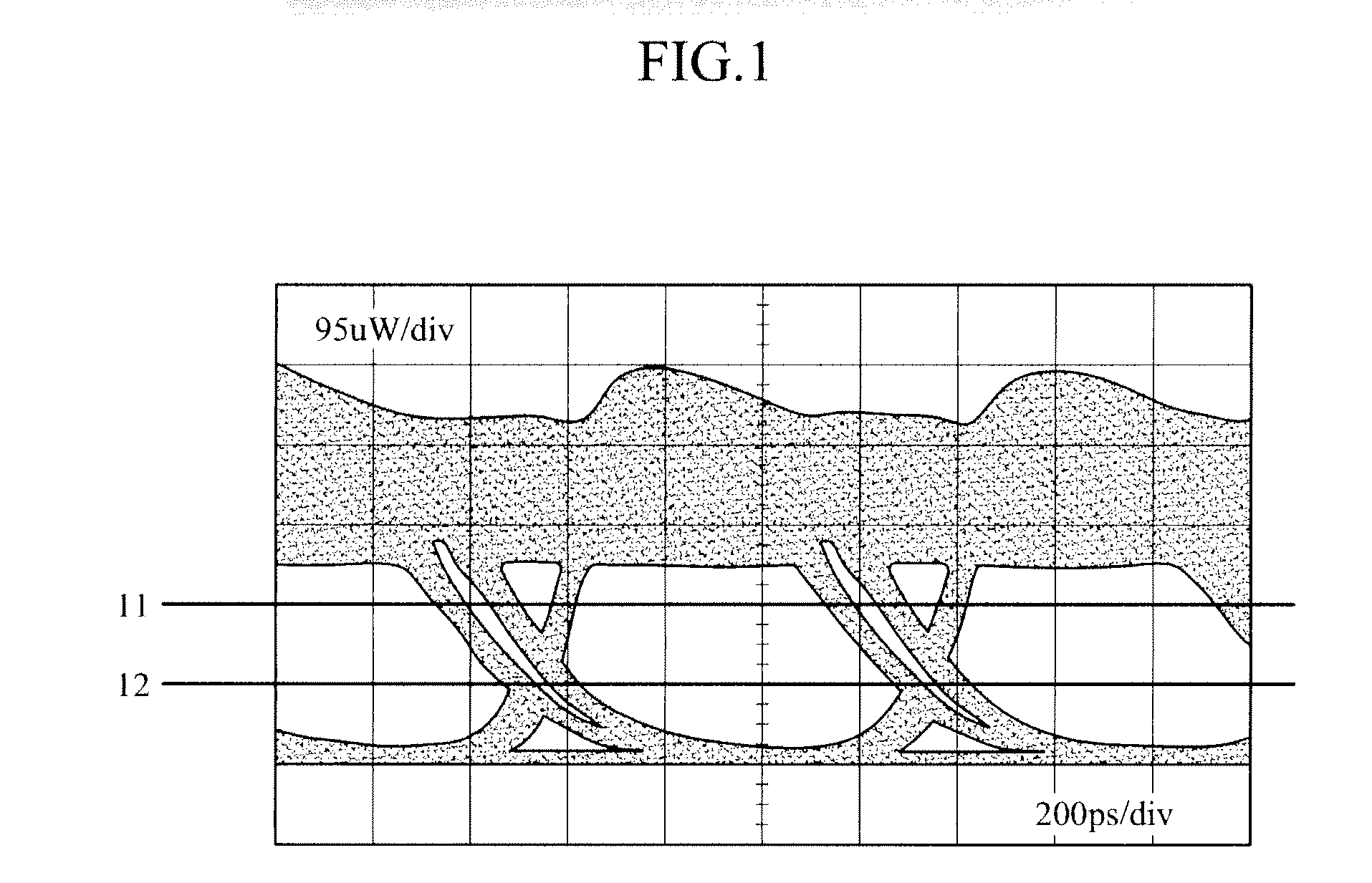
[0028]FIG. 1 is a diagram illustrating a received signal in a typical optical receiver. As shown in FIG. 1, noise components caused by conventional problems are mainly located at level “1” of an optical signal. It can be seen from an eye diagram of FIG. 1 that a re-modulated downstream optical signal causes a thickness of level “1” to become thicker than a thickness of level “0”. That is, an extinction ratio of the downstream optical signal appears to be greatly reduced due to a gain compression, which is one of characteristics of a refl...


PUM


Abstract

An optical receiver is provided which can be applied to a wavelength division multiplexing passive optical network (WDM PON) based on a reflective semiconductor optical amplifier employing a wavelength reuse scheme. The optical receiver includes a photo diode to convert an optical signal to an electrical signal; a pre-amplifier to linearly amplify the electrical signal and convert the amplified electrical signal to a voltage signal; a post-amplifier, which is equipped with a gain control function, to convert the voltage signal to a signal with a constant output level and to control a decision threshold of the converted signal; and an offset voltage generator to generate a predetermined offset voltage for the decision threshold control of the post-amplifier and to provide the offset voltage to the post-amplifier. Accordingly, it is possible to increase an extinction ratio of a downstream optical signal to a predetermined level in the WDM PON based on a reflective semiconductor optical amplifier employing a wavelength reuse scheme, and it is possible to reduce an optical power, which is received by the reflective semiconductor optical amplifier incorporated in a subscriber terminal, below a predetermined level. As a result, it is possible to improve transmission quality of the downstream and upstream optical signals.

Description

CROSS-REFERENCE TO RELATED APPLICATIONS[0001]This application claims the benefit under 35 U.S.C. §119(a) of Korean Patent Application Nos. 10-2008-0126809, filed on Dec. 12, 2008, and 10-2009-0022161, filed on Mar. 16, 2009, the disclosures of which are incorporated by reference in its entirety for all purposes.BACKGROUND[0002]1. Field[0003]The following description relates to an optical receiver and, more particularly, to an optical receiver in a wavelength division multiplexing passive optical network (WDM PON) based on a reflective semiconductor optical amplifier employing a wavelength reuse scheme.[0004]2. Description of the Related Art[0005]In a wavelength division multiplexing passive optical network (WDM PON) which employs a reflective semiconductor optical amplifier (RSOA) as an optical source of a central base station or of a subscriber terminal, RSOA is not wavelength-dependent. This has recently gained increased interest in that it helps solve handling of stored optical t...

Claims


Application Information

Patent Timeline
IPC IPC(8): H04B10/06H04J14/02
CPCH04B10/695H04J2014/0253H04J14/0282H04J14/02
Inventor CHO, SEUNG-HYUNKIM, BYOUNG-SHIPARK, MAN-YONG
Owner ELECTRONICS & TELECOMM RES INST
Why Eureka
Try Eureka