Position encoder and a method for detecting the position of a movable part of a machine

a technology of position encoder and movable parts, which is applied in the direction of converting sensor output, measuring devices, instruments, etc., to achieve the effect of efficient position dependent modulation of conductivity, high degree of flexibility, and modulation of conductivity within the section

Active Publication Date: 2010-06-24
VOGT ELECTRONICS COMPONENTS
View PDF23 Cites 60 Cited by
  • Summary
  • Abstract
  • Description
  • Claims
  • Application Information

AI Technical Summary

Benefits of technology

[0032]In addition to the advantageous effects described above, due to the lack of a magnetic core material in the coil external magnetic fields may not contribute to the magnetizing or saturation of the sensor assembly so that the outputs signals obtained may be moderately insensitive to strong magnetic fields, which may particularly occur in electric machines.
[0033]For this purpose the conductivity in the encoder is varied in an angle dependent manner so that a high degree of flexibility for the position dependent structuring of the encoder structure is obtained.
[0034]In one embodiment the conductive material is provided in the form of at least one trace or track that is passed by the coil upon moving the movable part. The at least one track may be provided according to various ways and at various appropriate positions, for instance outside of strong interfering fields, and the like. The track may be incorporated into a part of the rotor or the track may attached to the rotor by means of an appropriate support structure.
[0035]In one embodiment the track comprises a width that varies along the direction of movement so that an efficient position dependent modulation of the conductivity is accomplished.
[0036]In a further embodiment the at least one track comprises a constant width, at least within a section, so that the modulation of the conductivity within the section may be obtained by other measures, such as controlled adjustment of the sheet resistance, etc. By changing the width of different sections, each of which comprises a position dependent conductivity, a corresponding offset may be adjusted, thereby providing the possibility to additionally encode information into the at least one track.
[0037]In one illustrative embodiment an area fraction of an electrically conductive material varies within a section along the direction of motion, thereby obtaining an efficient modulation. For this purpose a specifically applied material may selectively be removed, or a base material of the rotor may appropriately be patterned in order to obtain the position dependent area fraction.

Problems solved by technology

This is particularly disadvantageous when the sensor is to be used in the automotive field, in which the sensor is exposed to harsh environmental conditions and motor currents up to 1 000 Ampere may occur.

Method used


Image

  • Position encoder and a method for detecting the position of a movable part of a machine
  • Position encoder and a method for detecting the position of a movable part of a machine
  • Position encoder and a method for detecting the position of a movable part of a machine

Examples


Embodiment Construction

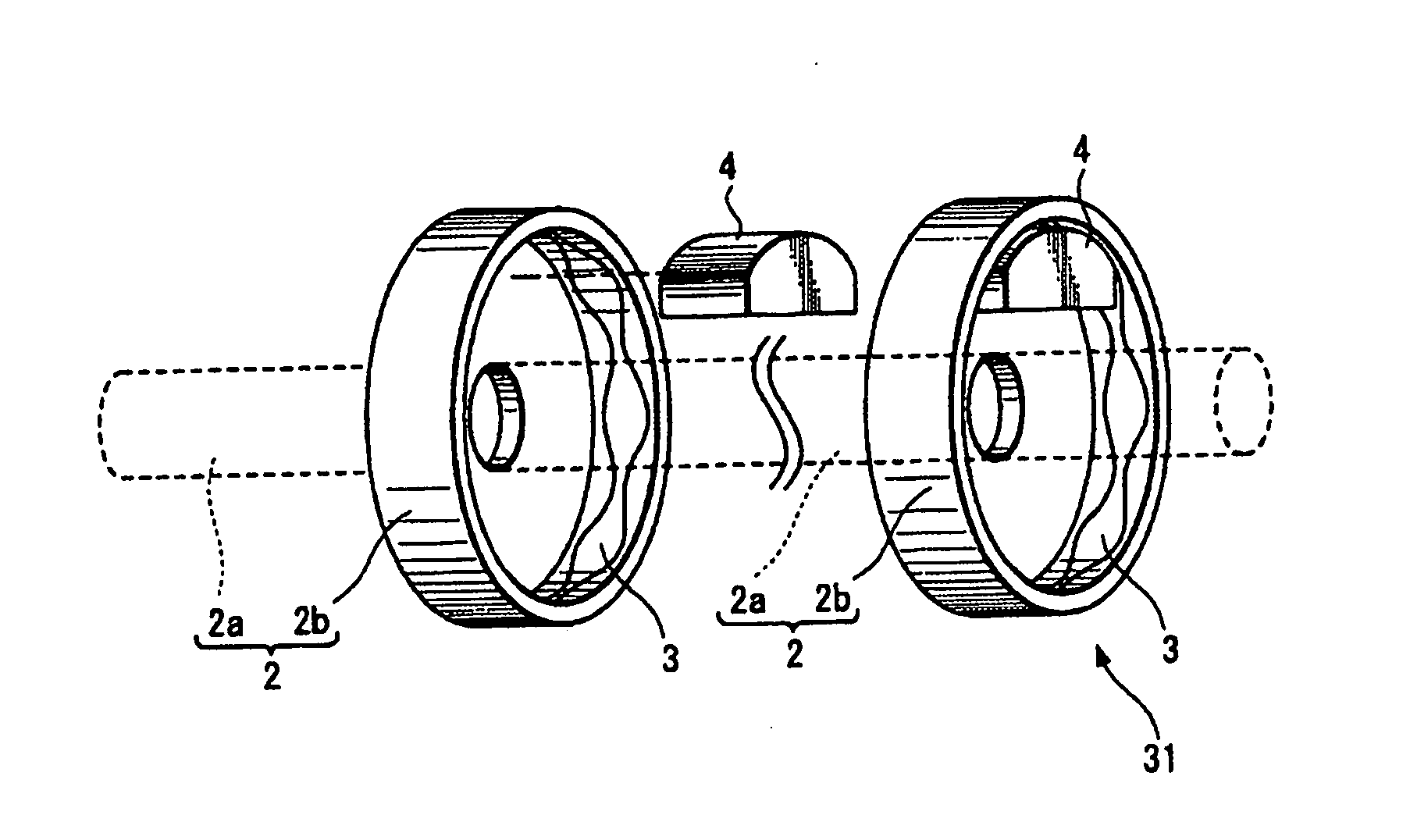
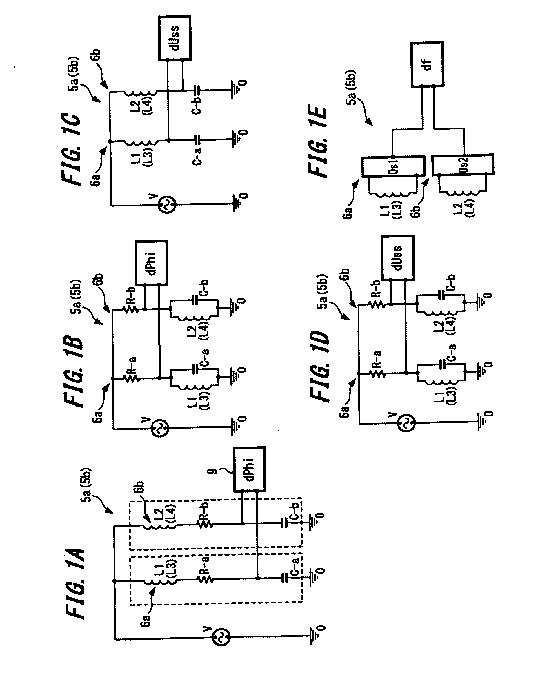
[0089]FIG. 1 A to FIG. 1 E show basic structures of sensor systems 5 used in an embodiment of the present invention.

[0090]The sensor system 5 is an inductive position sensor. This inductive position sensor is practically configured to have two resonance circuits 6a and 6b that are provided in a parallel configuration according to the embodiment of FIG. 1 A. The resonance circuit 6a includes a coil or inductance L1, a resistor R-a and a capacitor C-a, which are connected in series, and the resonance circuit 6b includes a coil or inductance L2, a resistor R-b and a capacitor C-b, which are connected in series.

[0091]It is desirable that the inductances L1 and L2 are provided in a planar type (planar form) configuration. The capacitors C-a and C-b are provided as separate devices in the embodiment shown exemplarily.

[0092]The voltage is supplied to the two resonance circuits 6a and 6b by an AC voltage source V that is connected in parallel with both resonance circuits. A frequency f of t...


PUM


Abstract

A rotation angle detection sensor system for a rotational body is provided, which has a reduced sensitivity against an interfering magnetic field and an interfering electric field. The rotation angle detection sensor system comprises an encoder structure that is attached to the rotational body of a machine and is movable along with this rotational body. A stationary sensor assembly is positioned opposite to this encoder structure and supplies at least one sensor signal for determining the angle position. The sensor assembly includes a first inductive element, the inductance of which is dependent on the angle position of the encoder structure.

Description

FIELD OF THE PRESENT INVENTION[0001]The present invention relates to a system and a method for detecting the position of a movable part, such as the rotor of a machine, in particular of an electric machine, comprising an encoder structure attached to the rotor and moveable in combination therewith and a stationary sensor assembly located in an opposing relationship to the encoder structure, wherein the sensor assembly provides at least one sensor signal from which the position may be derived.DESCRIPTION OF THE RELATED ART[0002]An apparatus and a method of the above-described type is known from WO 02 / 084849 A1. The device described in this document has a ring attached to the rotor with individual segments that are alternately magnetisable. Opposite to the magnetisable ring elements are provided stationary magnet sensor elements. The progression of the induction within the individual segments of the magnetisable sensor rings causes an alternate change of magnetisation in the sensor el...

Claims


Application Information

Patent Timeline
Patent Type & Authority Applications(United States)
IPC IPC(8): G01B7/30
CPCG01D5/2225G01D5/202G01D5/20
Inventor STRAUBINGER, FRANZBARTL, JOSEF
Owner VOGT ELECTRONICS COMPONENTS
Why Eureka
Try Eureka