Heat radiating member, circuit board using the heat radiating member, electronic component module, and method of manufacturing the electronic component module

Inactive Publication Date: 2010-06-24
TOYO TANSO KK +1
View PDF7 Cites 12 Cited by
  • Summary
  • Abstract
  • Description
  • Claims
  • Application Information

AI Technical Summary

Benefits of technology

[0048]The heat radiating member of the present invention comprises a material capable of varying its heat capacity to a desired heat capacity by varying manufacturing conditions, or a material (graphite sheet) capable of varying its heat capacity by controlling its bulk density. Therefore, it is unnecessary to increase or decrease the volume of the heat radiating member according to an increase or decrease of required heat capacity. As a result, it becomes possible to adjust the heat capacity without impairing its good space saving capability. Accordingly, an advantageous effect is exhibited that the degree of freedom in packaging electronic components increases while ensuring sufficient heat radiation characteristics.
[0049]In addition, with the graphite sheet, the heat radiating member can be manufactured, for example, by merely press-forming expanded graphite by compressing it (i.e., there is no constraint on the manufacturing method such as carbonizing a material such as polyimide). Therefore, the degree of freedom in shaping is high (i.e., a product with a desired shape can be manufactured easily). In this respect as well, the degree of freedom in packaging of electronic components is improved. Moreover, the heat radiating member c

Problems solved by technology

However, in this structure, heat needs to be released through the printed circuit board, so it is difficult to show high heat radiation capability.
In addition, the sheet made by treating a polymer substance such as polyimide at a high temperature treatment has a low degree of freedom in shaping (i.e.,

Method used


Image

  • Heat radiating member, circuit board using the heat radiating member, electronic component module, and method of manufacturing the electronic component module
  • Heat radiating member, circuit board using the heat radiating member, electronic component module, and method of manufacturing the electronic component module
  • Heat radiating member, circuit board using the heat radiating member, electronic component module, and method of manufacturing the electronic component module

Examples


example 1

[0073]In Example 1, the heat radiation effects were confirmed using heat radiating members made of various materials in a heat radiating structure that can effectively radiate heat generated by an LED module.

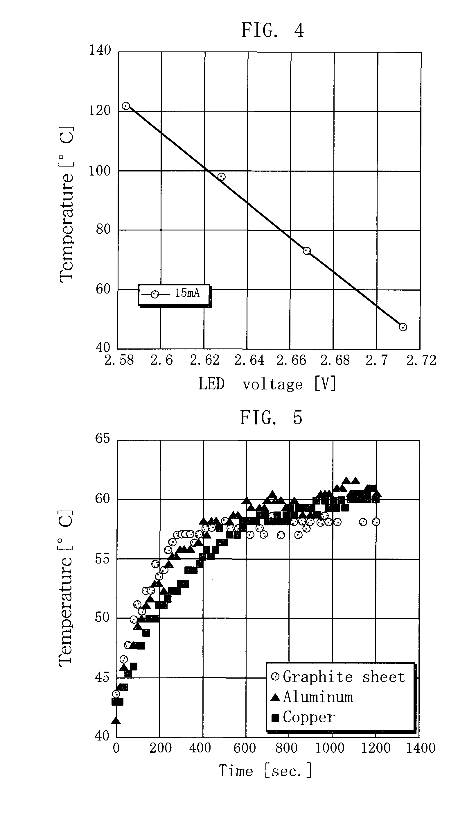
[0074]Generally, the maximum temperature at which an LED can be used is determined by the LED chip surface temperature (junction temperature: Tj). However, in reality, the temperature Tj cannot be measured directly.

[0075]Here, the LED has the feature that when the junction temperature increases, the forward voltage (Vf) decreases. Therefore, it was decided to measure the tendency of the change in the junction temperature by measuring the forward voltage (Vf).

[0076]The junction temperature can be calculated from the LED voltage obtained in a preliminary experiment and the profile of the junction temperature. From the results, the junction temperature can be calculated with certain accuracy.

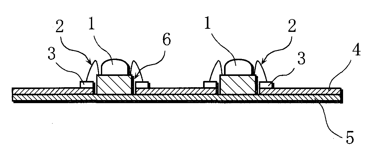
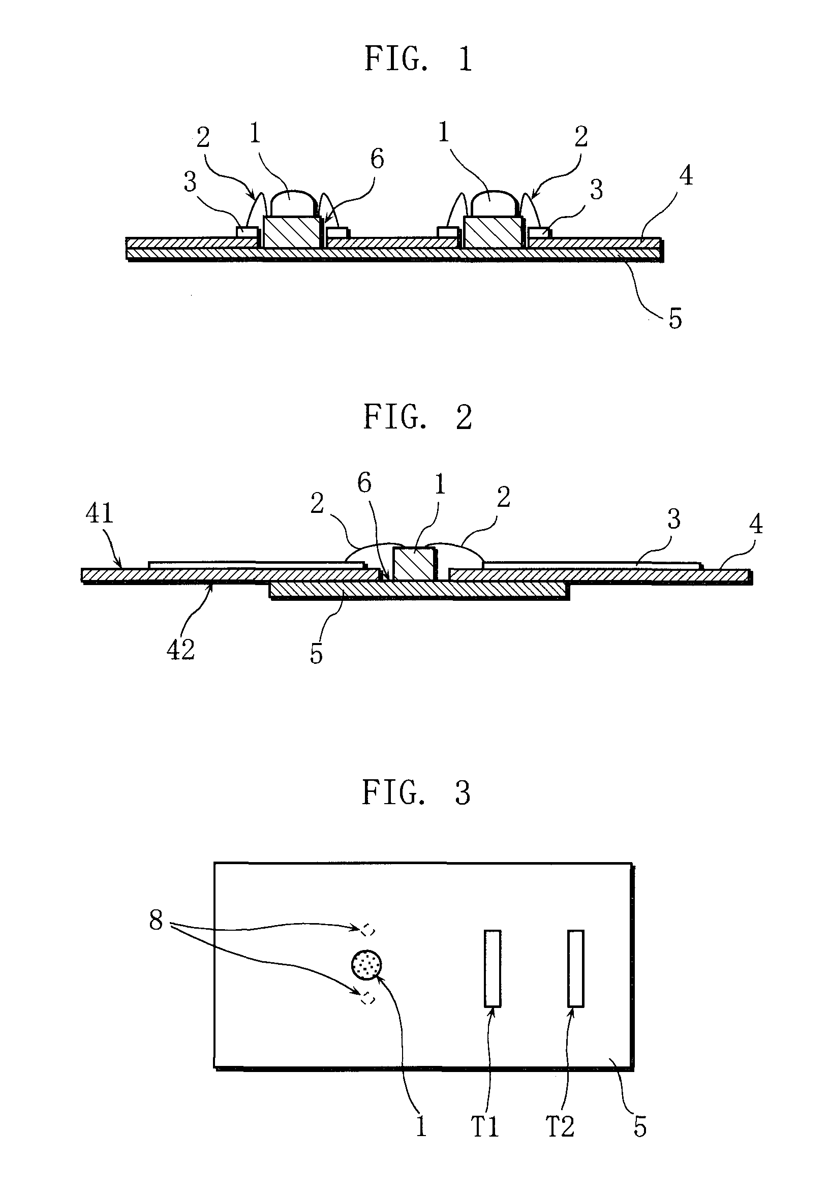
[0077]The LED module 1 used in the present example has the configuration in which a reflect...

example 2

[0091]In the present example, a temperature comparative test was conducted for graphite sheets having different areas. In the present example, 7 LED modules 1 as used in Example 1 were mounted on the substrate 4, as illustrated in FIG. 8. Silicon grease (G-747) was applied between the heat radiating member 5 and the LED modules 1. Application of the silicon grease can increase the area in which the heat radiating member and the LED modules are in close contact, so it is possible to obtain further higher heat radiation effects. The specification of the heat radiating member 5 is as follows, and other configurations are the same as in Example 1. Accordingly, all the graphite sheets had a bulk density of 2.0 Mg / m3 and a thickness D of 1.5 mm.

>

[0092]Manufacturer: Toyo Tanso Co., Ltd.[0093]Model: PF-150UHP[0094]Thickness: 1.5 mm[0095]Shape etc.:

experimental example 1

[0096](The shape is in a squared shape, the area is 430 cm2, and the mass is 129 g. Therefore, the heat capacity is 45.15 J / K.)


PUM

PropertyMeasurementUnit
Weightaaaaaaaaaa
Densityaaaaaaaaaa
Electrical conductoraaaaaaaaaa

Abstract

A circuit board using a heat radiating member that can cool an electronic component sufficiently without causing a substrate to break, increasing the total weight of the substrate, lowering the productivity, or increasing cost and device size. A circuit board has a substrate main body (4) having a wiring pattern (3) formed on a surface side, and a structure in which an LED module (1) is connected to the wiring pattern (3). The circuit board is characterized in that: a through hole (6) is provided in a portion of the substrate main body (4) so as to penetrate the substrate main body (4) from the surface side to a back side thereof; a heat radiating member (5) is provided on the back side of the substrate main body (4) so as to close one end of the through hole (6); and the LED module (1) is disposed in the through hole (6) so that the heat radiating member (5) and the LED module (1) are directly in contact with each other.

Description

TECHNICAL FIELD[0001]The present invention relates to a heat radiating member, a circuit board having a heat radiating structure using the heat radiating member, an electronic component module, and methods of manufacturing them. More specifically, the invention relates to a heat radiating member made of a material that can be manufactured to have a varying heat capacity or the like, a circuit board and an electronic component module that have a heat radiating structure that is space saving, lightweight, low in cost and moreover capable of adjusting heat radiation capability. The invention further relates to manufacturing methods of them.BACKGROUND ART[0002]A known conventional heat radiating structure for a circuit board has the following configuration. Metallic wiring lines are provided on one side of a substrate and electronic components are mounted on the wiring lines. A heat radiating plate made of copper, aluminum, or the like is in surface contact with the back side of the sub...

Claims


Application Information

Patent Timeline
IPC IPC(8): F21V19/00H05K1/00H05K7/20F28F7/00H05K3/30
CPCH01L23/13Y10T29/4913H01L33/641H01L2224/48091H01L2224/48227H01L2924/01004H01L2924/01012H01L2924/15153H01L2924/1517H05K1/021H05K1/182H05K3/0058H05K2201/0323H05K2201/10106H01L23/373H01L2924/12041H01L2924/01019H01L24/48H01L2924/00014H01L2924/00H01L2224/451H01L2224/45099H01L2924/00012H01L23/12H05K1/02
Inventor HIROSE, YOSHIAKIYUKI, TETSUYAMISAKI, YUKINORIARAKAWA, MASATERU
Owner TOYO TANSO KK
Why Eureka
Try Eureka