When in an operating position, downdraft vent arrangements known in the art are also limited in this respect.
However, existing cooling systems do not account for the temperature of the incoming air, i.e., the systems are directed toward air removal from the inside the housing without considering the surrounding
air temperature.
Further, many existing systems re-circulate the previously expelled heated air back into the housing cavity, thereby increasing the temperature inside.
This may result in elevated temperature levels in the housing that may cause component failure and / or reduced cooking performance.
However, when used in combination with gas on glass surface units, the downdraft-induced air flow at the cook top surface tends to interfere with the gas
flame.
The fan has been found to be the least expensive and most reliable cooling solution.
The known drawback here, though, has been the sensitivity of the air flow, disruption of which causes failure or reduced energy for operation of the
induction system.
Failure to keep the generator cool results in loss of power to the cooking product all the way to a complete unit shutdown.
While the use of a
fan in this manner is desirable in preventing heat-caused damage to the electronic components employed, it is also considered a
disadvantage.
The use of a fan has two issues when used for cooling an induction cook top.
When a fan is used in this manner,
noise associated with the fan's operation is present whenever a cook top with induction of the type is used.
Many users find this
noise to be objectionable.
Further, the use of a fan alone is considered a problem because if air flow is blocked, the unit must be completely
shut down for safety reasons.
However, a user does not take into consideration whether or not there is heat buildup present within a housing, rather only noting that the unit failed to operate.
Although it is possible to use other methods to keep the temperature down, e.g., by the use of thermostats and various related known
temperature sensing apparatus for controlling the flow of current in an electrical circuit, it is known that such expedients are undesirable for any of a variety of reasons, including effectiveness, cost, and reliability.
The plenum does not, in some cases, provide any sealing to prevent the drawing of air from the box.
With all this bending of the air
stream, air is lost.
Thus, large amounts of draw / vacuum / suction are needed to overcome all these losses.
With the need for more draw / vacuum / suction comes a larger fan / blower motor, which increases costs,
noise, size, and weight.
However, the light construction of the forward curved blade does not permit this wheel to be operated at speeds needed to generate high static pressures.
A drawback to this type is that it must be designed for twice the speed, which increases the cost of the unit.
Myths of why include: they cannot provide the static pressures needed for drawing / vacuum / suction, size, and spacing requirements.
Without the aperture, the fan is not truly a
propeller fan, since it cannot positively move air from one space to another.
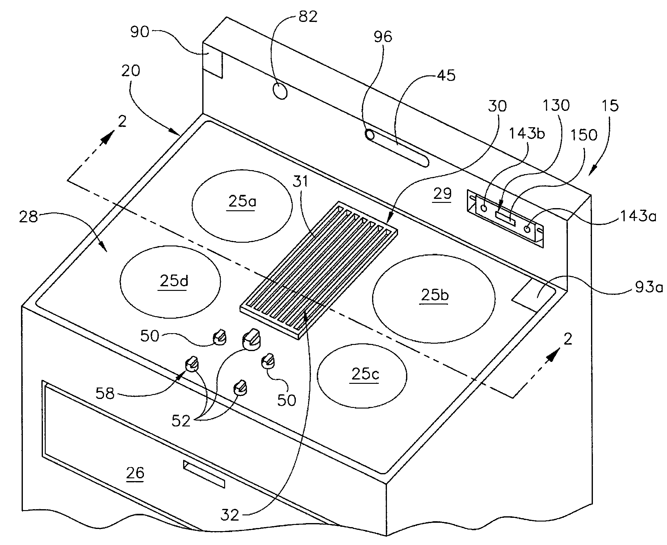
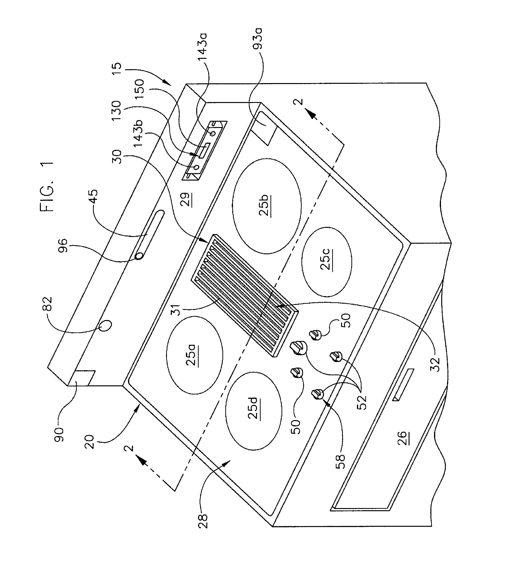
The present downdraft ventilator designs also present problems when integrated into a cook top.
Because of the low profile, spilled food and liquids can enter the grate, and removal of the items that are not captured by the filter cannot be removed easily.
The present design of ventilators is also often large and bulky.
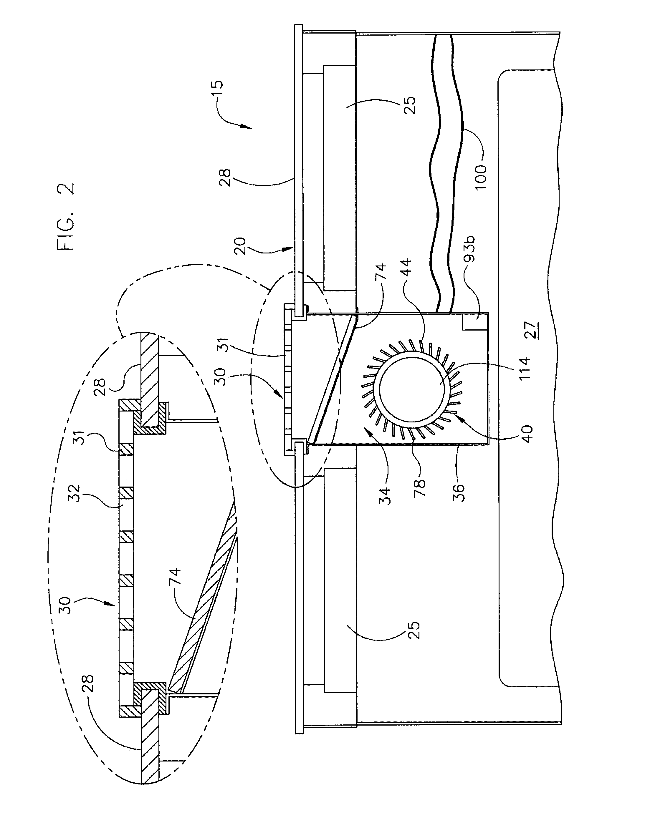
There, the space below the unit is not available for a user to use for storage due to the centrifugal blower below and the size of the plenum presently used.
This also limits the downdraft ventilators from being used as a freestanding unit, as a mobile unit, used in a cabinet (e.g., suspended), or in areas that do not have the ability to support a large structural frame below.
For example, with the use of
induction heating cooking stoves, even a weak side draft caused the cooking contaminants to move outside the exhaust vent because there was not enough energy to raise the air up for the collection to take place.
These results show that when induction-heating cooking equipment was used in a real commercial kitchen environment where the room air was disturbed, oil
smoke or other cooking contaminants were not fully removed by the exhaust vent.
However, this type of localized sensor has very localized action and does not take into account the entire surface area of the generators /
inductor.
If the sensor does not work properly, there are situations in which the critical temperature may be reached and even exceeded causing damage.
The prior art primarily is directed to controlling the operation of an internal electric fan for cooling the
induction heating cooking apparatus, but it fails to address the flow of
ambient air outside the housing.
However, this system does not address the issue of the surrounding air intake and the temperature or quality of the air that is brought back into the housing for cooling.
However, this system relies upon the critical factor that the
airflow must be undisturbed in cooling.
The problem with this design is that the
cartridge does not take into account the exhausted air or the air that is brought into the system.
However, this design is flawed because air that is drawn in will take the path of least resistance, i.e., the air would not be drawn effectively from the
cartridge.
Without proper air flow, the generator in the induction
cartridge would overheat which may result in component failure or destruction.
This system can be large, complex, and take up large amounts of space.
Moreover, this system does not treat the incoming air.
This design does not take into account where the air is exhausted and the potential of drawing the exhausted air back into the cavity.
However, it was found that this approach was incapable of protecting the
inverter when loaded with a highly conductive utensil due to the heat buildup.
Again, issues still remained as to the cooling requirements needed with different types of loads.
As such, controls increase the
operating frequency in response to a decreased conductive interval (as is normally caused by loading of the
inverter) and they are not particularly suited to protecting the
inverter from improper loads.
In certain instances, presenting a highly conductive utensil to the work area causes a substantially shortened conductive interval, which, in turn, causes the constant
duty cycle control to raise the
operating frequency even higher, thus further aggravating the situation.
The end result is increased temperature and the need for more air flow to cool the unit down.

