Electronic module and method for manufacturing an electronic module

a technology of electronic modules and manufacturing methods, applied in the field of electronic modules, can solve the problems of reducing the number of manufacturing steps needed to manufacture electronic modules, and limiting the footprint of modules extrusion coated in this manner, and achieve the effect of increasing the component density in terms of the footprin

Inactive Publication Date: 2010-07-08
ROBERT BOSCH GMBH
View PDF4 Cites 11 Cited by
  • Summary
  • Abstract
  • Description
  • Claims
  • Application Information

AI Technical Summary

Benefits of technology

[0005]To increase component density with regard to a footprint of the electronic module, it is provided in accordance with the present invention that at least one further second substrate, which is provided with second electrical leads, is embedded in the housing, the second leads being designed as a second pressed screen, and the two pressed screens being directly connected to each other in at least one location. The first substrate and the first pressed screen form a first structural unit, and the second substrate and the second pressed screen form a second structural unit. The substrates situated on different levels are wired via the assigned pressed screens. These pressed screens therefore have the function of providing external contacting of the substrates and their electronic components and they may alternatively and / or additionally contact the substrates to each other. Furthermore, the pressed screens provide additional support for the assigned substrates. This is advantageous, in particular, before the substrates are embedded in the housing.

Problems solved by technology

The modules extrusion coated in this manner are limited in terms of their footprint by the technical conditions present during shaping, for example the geometry of the injection mold, the filling heights and the flow behavior of the plastic used for extrusion coating, and by the spatial conditions.
Expanding the electronic module onto multiple levels requires a complex structure having additional wiring levels, which substantially increases the number of manufacturing steps needed to manufacture the electronic module.

Method used


Image

  • Electronic module and method for manufacturing an electronic module
  • Electronic module and method for manufacturing an electronic module
  • Electronic module and method for manufacturing an electronic module

Examples


Embodiment Construction

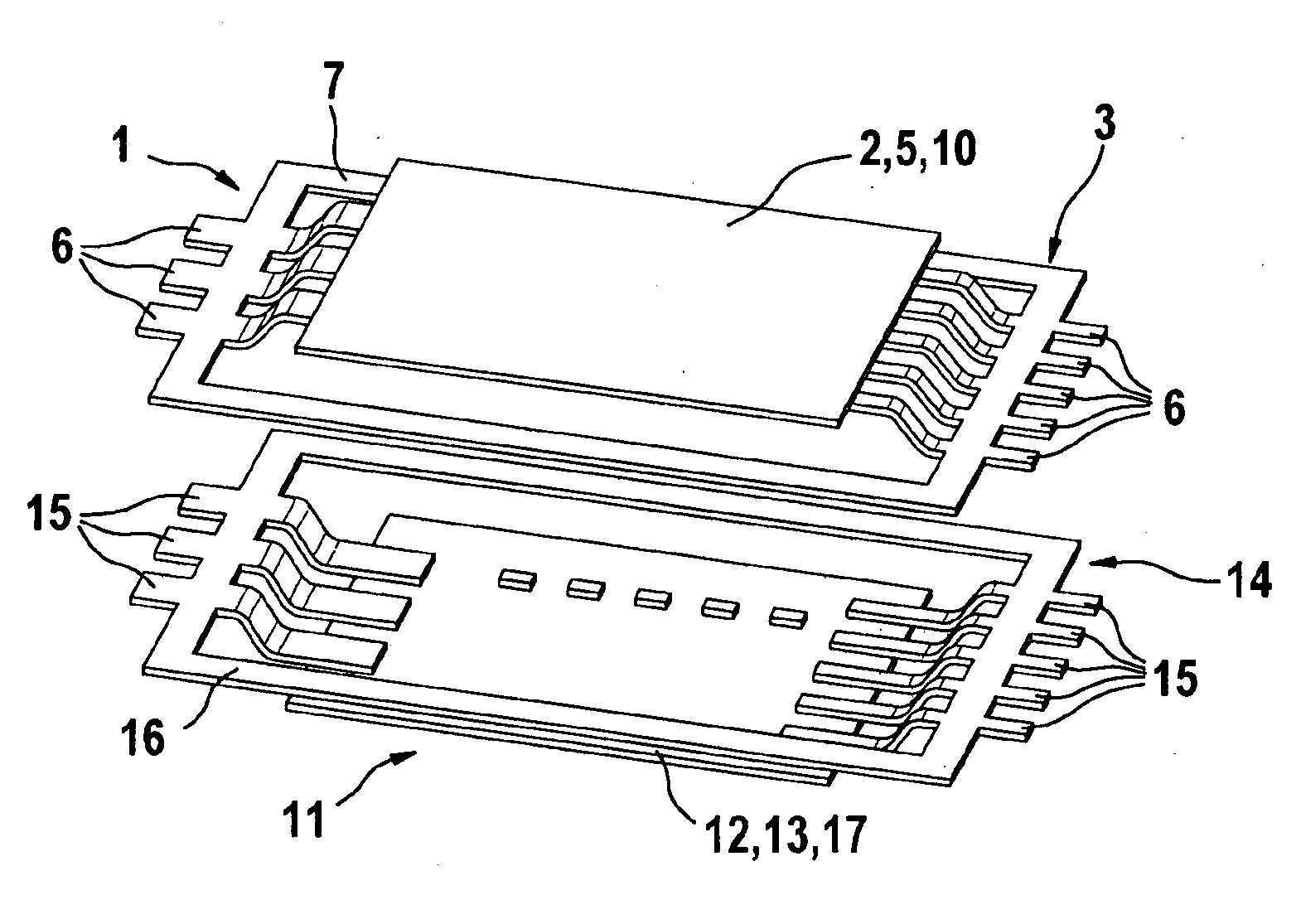
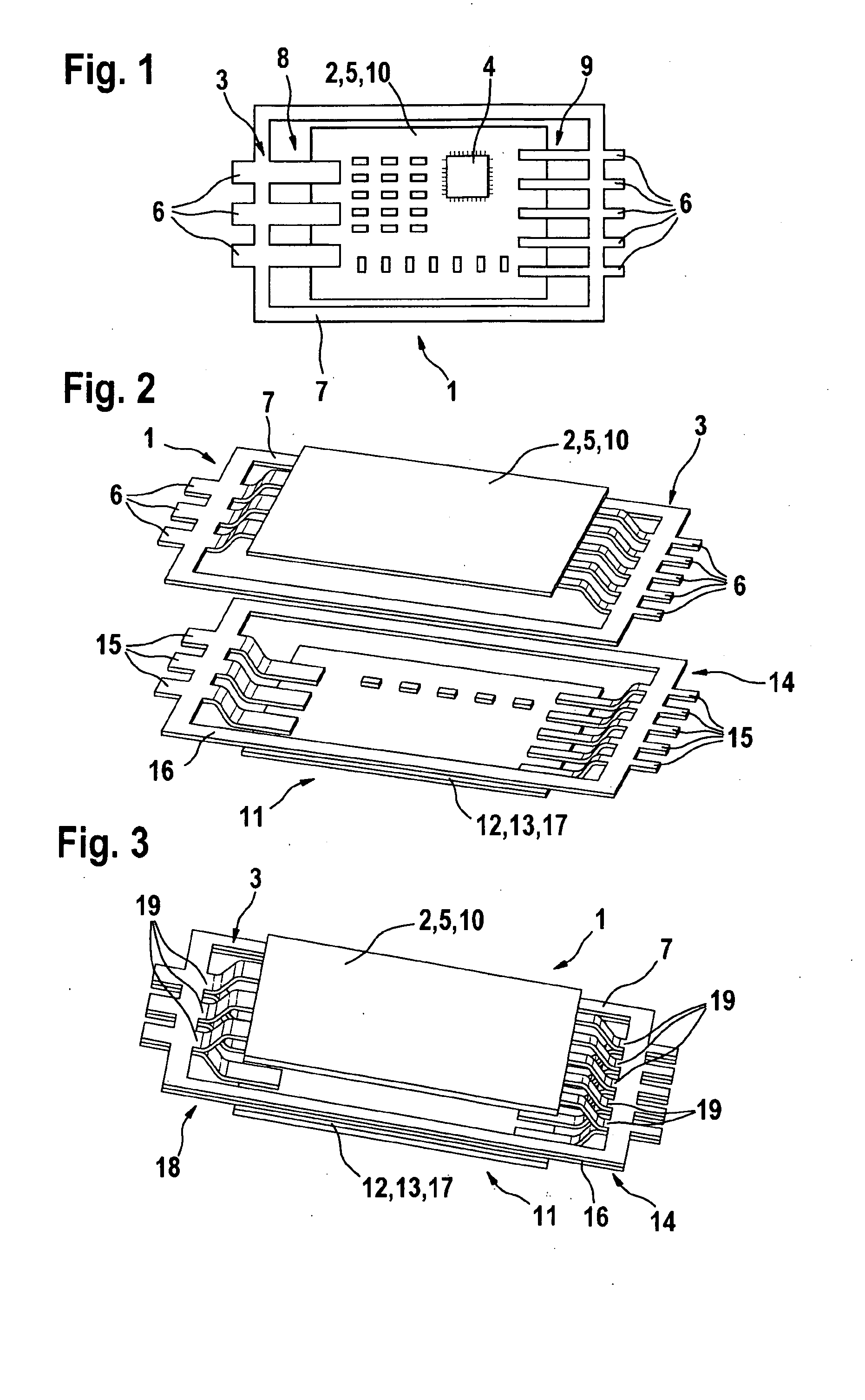
[0027]FIG. 1 shows a top view of a first structural unit 1, including a component-mounted first substrate 2 and a pressed screen 3. Substrate 2 has electronic components 4, only one of which is illustrated to simplify the representation. First substrate 2 is designed as a circuit board 5 having conductor tracks which are not illustrated. The conductor tracks are used to interconnect electronic components 4 within circuit board 5 and to provide contact surfaces for contacting first leads 6 of pressed screen 3. Explicitly illustrated component 4 is glued onto first substrate 2 and connected to the conductor paths (not shown) by bonding for the purpose of electrical contacting. Alternatively, electronic component 4 is glued onto first substrate 2. First pressed screen 3 has first leads 6 and a first additional structure 7 which connects first leads 6 and completely surrounds substrate 2 of finished structural unit 1. First leads 6 are situated within first structural unit 1 in such a w...


PUM

PropertyMeasurementUnit
electricalaaaaaaaaaa
mechanicalaaaaaaaaaa
electricallyaaaaaaaaaa

Abstract

An electronic module includes a first substrate having at least one electronic component, and a housing embedded in the substrate and designed as an injection molded housing or a transfer molded housing, and which includes electrical leads protruding from the housing, connected to the first substrate and designed as a pressed screen. At least one further second substrate provided with second electrical is embedded in the housing, the second leads being designed as a second pressed screen, and the two pressed screens being directly connected to each other in at least one location.

Description

BACKGROUND OF THE INVENTION[0001]1. Field of the Invention[0002]The present invention relates to an electronic module including a first substrate, which has least one electronic component, a housing embedded in the substrate and designed as an injection molded housing or a transfer molded housing, and including electrical leads protruding from the housing, which are connected to the first substrate and designed as a pressed screen.[0003]2. Description of Related Art[0004]An electronic module of this type is known. The substrate of the electronic module has at least one electronic power component and / or logic component. In terms of its outer contacting, the substrate is connected in an electrically conductive manner to leads which are designed as a pressed screen. To protect the electronic component-mounted substrate, the substrate is embedded in an injection molded housing or a transfer molded housing, together with the areas of the leads which are connected to the substrate. The mo...

Claims


Application Information

Patent Timeline
Patent Type & Authority Applications(United States)
IPC IPC(8): H05K1/03H05K3/36H05K1/16H05K1/11
CPCH01L23/49531Y10T29/49213H01L23/49551H01L25/16H01L2924/09701H05K1/0306H05K1/144H05K3/284H05K2201/0379H05K2201/042H05K2201/1034H05K2201/10924H05K2203/1316H01L2924/0002H01L23/49537Y10T29/49126H01L2924/00
Inventor KIMMICH, PETERNGUYEN, QUOC-DAT
Owner ROBERT BOSCH GMBH
Why Eureka
Try Eureka