In Vitro Microfluidic Model of Microcirculatory Diseases, and Methods of Use Thereof

Inactive Publication Date: 2010-07-08
PRESIDENT & FELLOWS OF HARVARD COLLEGE +2
View PDF7 Cites 19 Cited by
  • Summary
  • Abstract
  • Description
  • Claims
  • Application Information

AI Technical Summary

Benefits of technology

[0010]Remarkably, because the devices of the invention are fabricated using standard microfabrication techniques, the invention provides a

Problems solved by technology

However, an in vivo approach does not allow one to vary systematically parameters of interest (channel dimensions, oxygen concentrations), is inherently lo

Method used


Image

  • In Vitro Microfluidic Model of Microcirculatory Diseases, and Methods of Use Thereof
  • In Vitro Microfluidic Model of Microcirculatory Diseases, and Methods of Use Thereof
  • In Vitro Microfluidic Model of Microcirculatory Diseases, and Methods of Use Thereof

Examples


Example

Example 1

[0156]Blood Specimens. Blood specimens were collected during the normal course of patient care at Brigham and Women's Hospital and used in experiments in accordance with a research protocol approved by the Partners Healthcare Institutional Review Board. Blood samples were collected in 5 mL EDTA vacutainers and stored at 4° C. for up to 60 days. Hematocrit was determined using a Bayer Advia 2120 automated analyzer (Bayer, Tarrytown, N.Y.). Hemoglobin fractions were determined using cellulose agar electrophoresis and confirmed by HPLC using a Tosoh G7 column (Tosoh, Tokyo, Japan).

Example

Example 2

[0157]Fabrication of Microfluidic Devices. A multilayered microfluidic network was fabricated in poly(dimethylsiloxane) (PDMS) using previously described soft lithography techniques. Duffy, D., J. McDonald, et al. (1998). “Rapid prototyping of microfluidic systems in poly(dimethylsiloxane).”Analytical Chemistry 70(23): 4974-4984. The multilayered device consists of a 150 μm thick gas reservoir separated from a 12 μm vascular network by a 150 μm PDMS membrane. SU8 photoresist (Microchem, Newton, Mass.) was used to fabricate the mold masters for both the vascular and gas channels. The vascular network was fabricated to be 12 μm thick by spin coating SU8-2015 onto a 4-inch silicon wafer at 3000 rpm for 30 seconds. This wafer was then softbaked at 65° C. for 1 minute and 95° C. for two minutes. Next the SU8 coated substrate was placed into soft contact with a high-resolution transparency photomask and exposed with UV (365 nm) light at 100 mJ / cm2. This substrate was then hardbak...

Example

Example 3

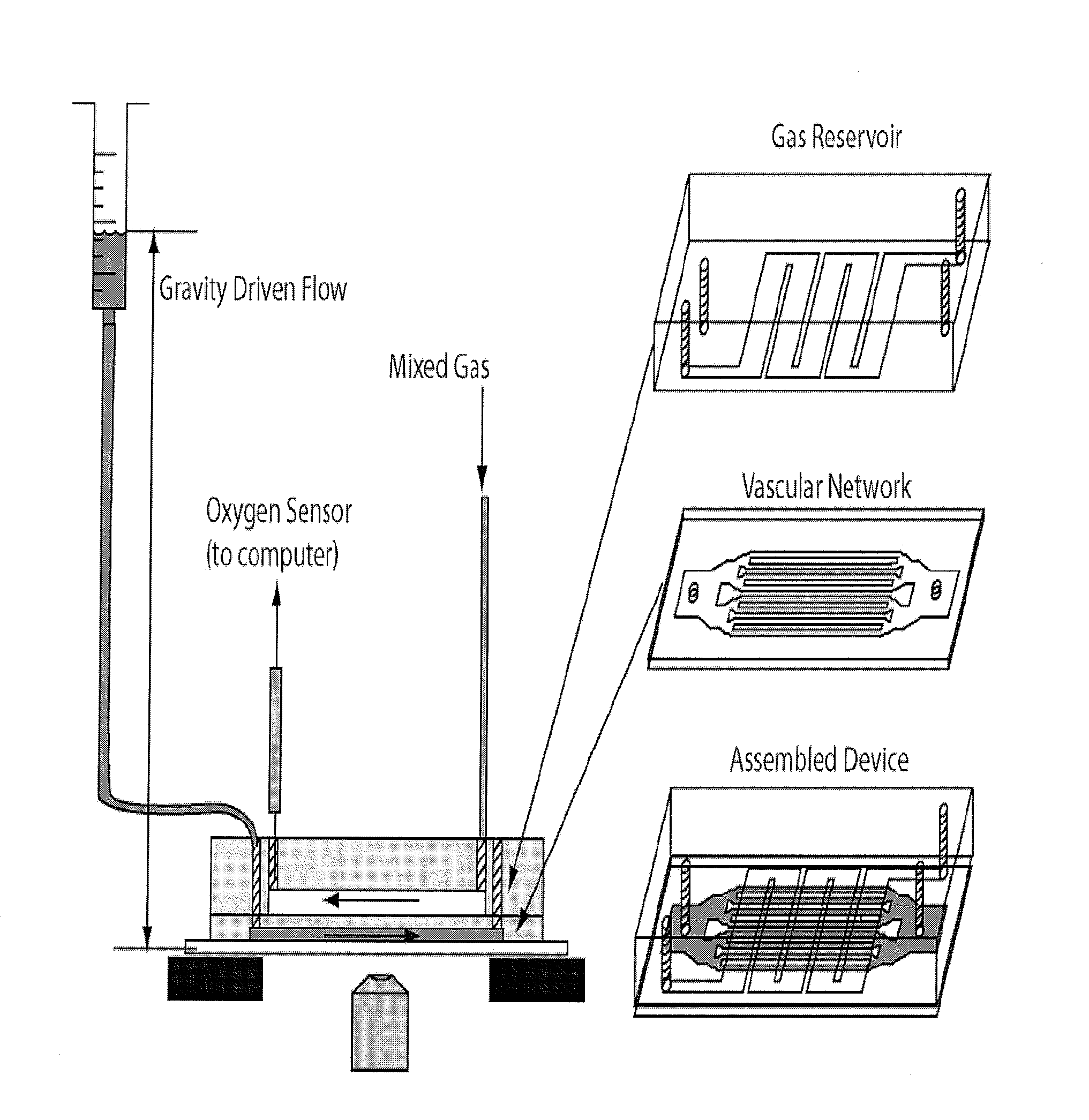
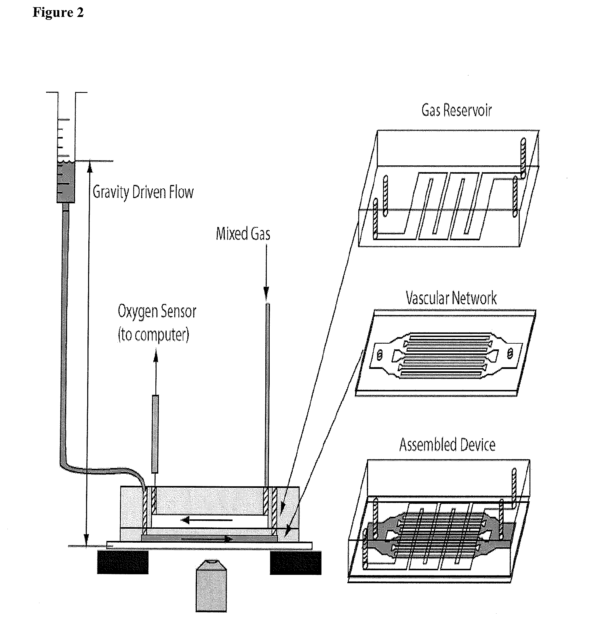
[0159]Experimental Setup. The assembled microfluidic device was mounted on an inverted microscope (Nikon TE-3000) and the fluidic and gas sources were connected as shown in FIG. 2. The microfluidic channels begin 4 mm wide, then split into roughly equal total cross section areas until the smallest dimension (7, 15, 30, or 60 μm) which then traverses 4 cm until the channels recombine sequentially at the outlet. The blood velocity was monitored most often in the 250 μm channels which were fed by 4 60-μm, 8 30-μm, 16 15-μm, or 16 7-μm channels depending on the device studied. Two rotometers controlled the gas mixture fed through the oxygen channels. The gas mixture diffuses rapidly through PDMS to initiate occlusion or flow. The outlet gas concentration was monitored with a fluorescent oxygen probe (FOXY Fiber Optic Oxygen Sensor, Ocean Optics, Dunedin, Fla.) to monitor the gas concentrations within the gas microchannels. Gravity-driven flow was used to inject blood into the v...


PUM

PropertyMeasurementUnit
Thicknessaaaaaaaaaa
Thicknessaaaaaaaaaa
Thicknessaaaaaaaaaa

Abstract

One aspect of the invention relates to a microfluidic device which recreates important features of the human microcirculation on a microscope stage. In certain embodiments of the invention, the clinical scenario associated with ‘sickle cell crisis’ whereby blood vessels are occluded in various organs causing pain and tissue damage can be recreated. In certain embodiments, one can use a device of the invention to study the processes that lead to crisis, and screen therapies (such as small molecules) that might be used to prevent crisis. Further, certain embodiments of the invention allow one to study and screen therapies for a range of human blood disorders, such as hereditary spherocytosis, disorders of white blood cells, such as Waldenstrom's macroglobulinemia or leukocytosis, disorders of blood platelets and coagulation, such as hemophilia A and B, activated protein C resistance, and essential thrombocythemia.

Description

RELATED APPLICATIONS[0001]This application claims the benefit of priority to United States Provisional Patent Application Ser. No. 60 / 900,242, filed Feb. 8, 2007; the entirety of which is hereby incorporated by reference.GOVERNMENT SUPPORT[0002]This invention was made with support provided by the National Institutes of Health (Grant No. F32DK072601-01); therefore, the government has certain rights in the invention.BACKGROUND OF THE INVENTION[0003]There are very few existing microfluidic models of disorders of blood flow. In particular, there are very few, if any, in vitro models of sickle cell crisis or vaso-occlusion (blockage of blood vessels). While several patents discuss sickle cell disease and microfluidic devices (such as U.S. Pat. Nos. 7,015,030; 6,960,437; 6,613,525; 6,344,326; 6,326,211; 6,074,827; and 6,007,690; all of which are incorporated by reference), none of these patents discloses a method for studying sickle cell disease or blood disorders in general. Instead, the...

Claims


Application Information

Patent Timeline
IPC IPC(8): G01N27/26G01N27/447
CPCB01L3/5027B01L2300/0816B01L2300/10B01L2400/0406C12M23/16B01L2400/0415B01L2400/0487G01N2800/224B01L2400/0409
Inventor BHATIA SANGEETA N.EDDINGTON DAVID T.HIGGINS JOHN M.MAHADEVAN LAKSHMINARAYANAN
Owner PRESIDENT & FELLOWS OF HARVARD COLLEGE
Why Eureka
Try Eureka