Packaging container and apparatus and method for manufacturing same
- Summary
- Abstract
- Description
- Claims
- Application Information
AI Technical Summary
Benefits of technology
Problems solved by technology
Method used
Image
Examples
embodiment 1
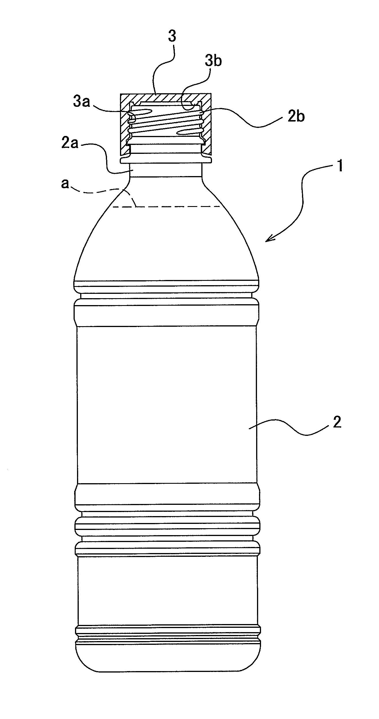
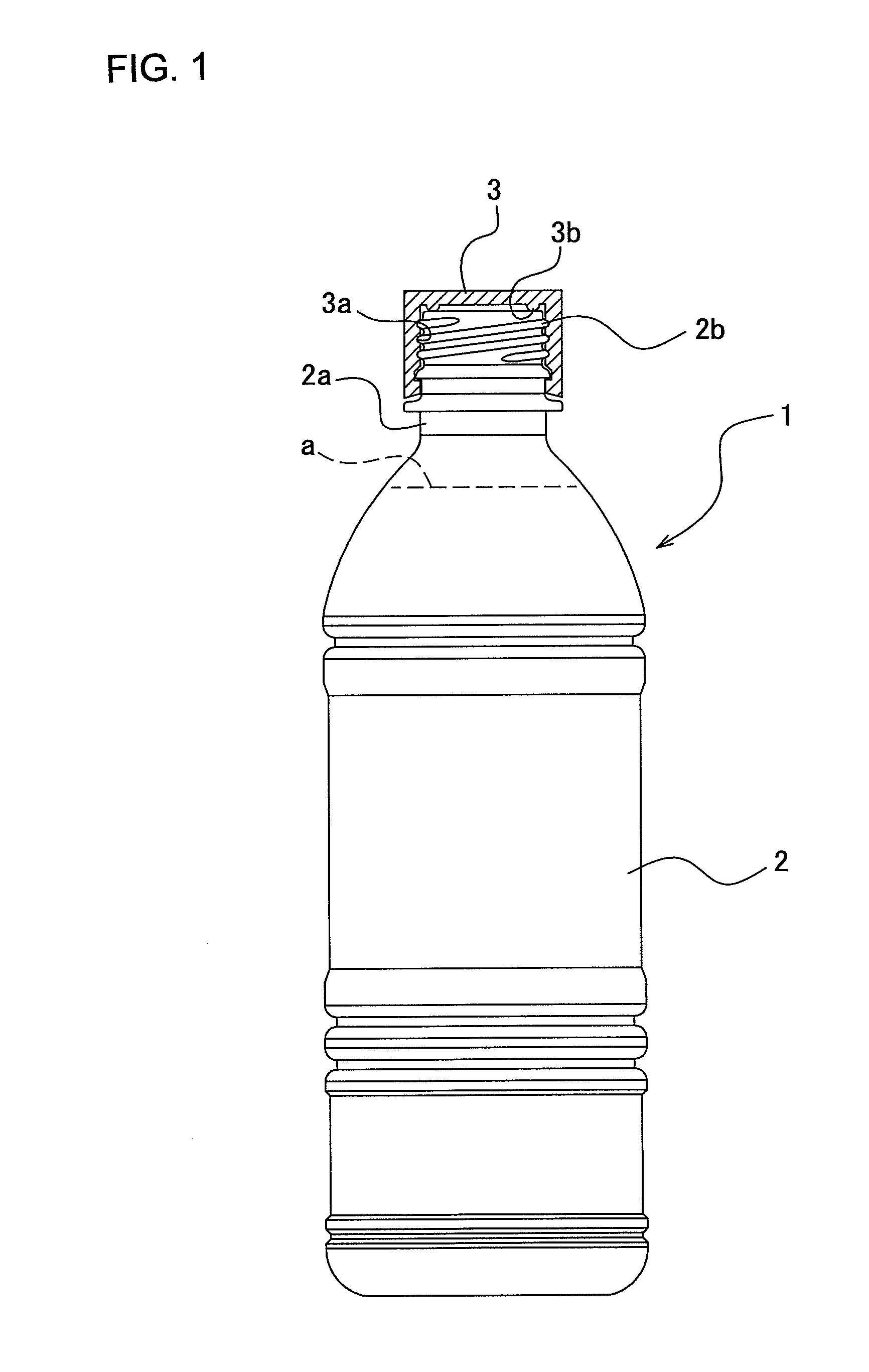
[0125]As shown in FIG. 1, the packaging container or body 1 includes a bottle 2 as a container and a cap 3 as a lid. A male thread 2b is formed to a mouth portion 2a of the bottle, and a female thread 3a is also formed to the cap 3, and the mouth portion 2a of the bottle 2 is sealed through engagement of the male and female threads 3a and 2b.
[0126]The bottle 2 is formed through a blow-formation or molding of a preform made of PET, not shown, having approximately test tube shape. The bottle 2 may be formed of another resin material such as polypropylene, polyethylene or other without being limited to PET resin. The preform is molded through an injection molding process or like and is provided with an approximately test tube-shaped body and a mouth portion 2a of the bottle 2. The mouth portion 2a is formed with a male thread 2b at the same time as the preform injection molding time. The cap 3 is formed of a resin material such as polypropylene or like through an injection molding pro...
second embodiment 2
[0178]As shown in FIG. 6, in this embodiment 2, different from the first embodiment 1, wheels 11b and 11c are arranged between the introducing conveyer 11a and the wheel 12, and these wheels 11b and 11c are accommodated in the first aseptic chamber 23. The bottle 2 is conveyed from the introducing conveyer 11a to the wheel 11c through the wheel 11b, and sterilized by blowing the hydrogen peroxide gas “b” from a nozzle 75 while moving around the wheel 11c. Then, the bottle 2 reaches the wheel 12 through a wheel 11d and is sterilized by the heated water while moving around the wheel 12.
[0179]As shown in FIG. 7, the wheel 11c is mounted to a turning (swiveling) shaft 61 standing upward from a machine table 60 to be rotatable around the swiveling shaft 61. A support column 61a stands upward from a plate surface of the wheel 11c and a manifold 62 for jetting the hydrogen peroxide gas “b” is secured to the upper tip end portion of the column 61a. A conduit 63 extends upward on an extensio...
third embodiment 3
[0190]As shown in FIG. 8, a container of a packaging container 28 in this third embodiment 3 is formed as a pressure-resistant bottle having a petal shaped bottom-type or champagne-type bottom portion 2c. This bottle 2 is filled up with a beverage “a” having a nature for pressurizing the interior of the bottle with a gas, such as lactic carbonated drink, fruit-contained carbonated drink, colored-fruit carbonated drink or like.
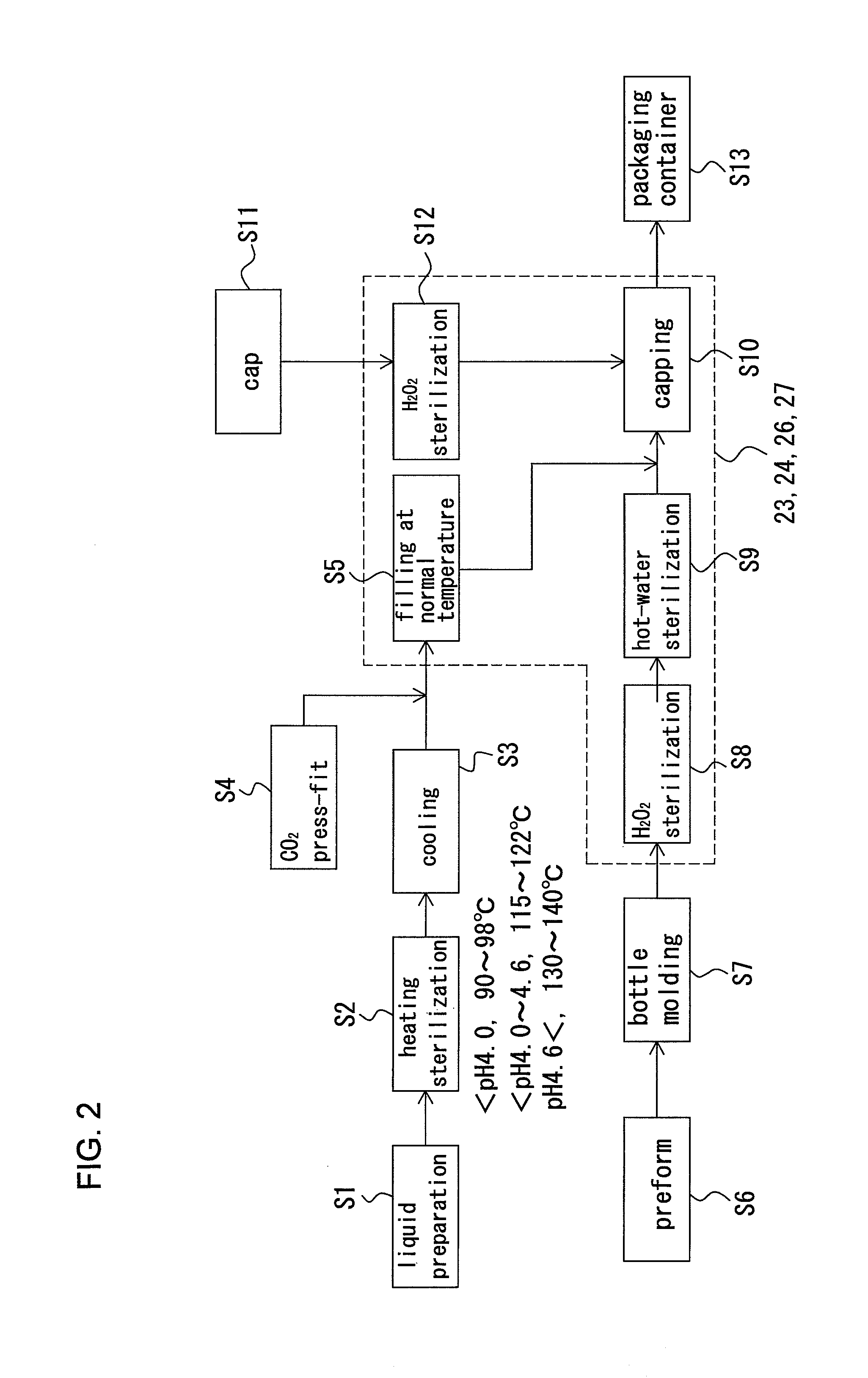
[0191]As shown in FIG. 2, this beverage “a” is heated and sterilized (step 2), cooled (step 3), and thereafter, pressurized by applying carbonate gas (step 4). Then, the beverage fills the bottle 2 having a petal shaped bottom-type or champagne-type bottom portion 2c (step 5), and thereafter, substantially the same steps as those mentioned with reference to the first embodiment may be performed to manufacture the packaging container 28.
[0192]It is further to be noted that, with reference to this third embodiment, like reference numerals are added to members or ...
PUM
 Abstract
Description
Claims
Application Information
 - R&D
- Intellectual Property
- Life Sciences
- Materials
- Tech Scout
- Unparalleled Data Quality
- Higher Quality Content
- 60% Fewer Hallucinations
Browse by: Latest US Patents, China's latest patents, Technical Efficacy Thesaurus, Application Domain, Technology Topic, Popular Technical Reports.
© 2025 PatSnap. All rights reserved.Legal|Privacy policy|Modern Slavery Act Transparency Statement|Sitemap|About US| Contact US: help@patsnap.com


