One-step method for the production of nanofluids

a nanofluid and one-step technology, applied in the field of one-step method and system for the manufacture of nanofluids, can solve the problems of inability to achieve the effect of reducing the amount of time, reducing the distance between the hbe and the hbe, and reducing the size of the nanoparticles incorporated

Inactive Publication Date: 2010-07-08
THE UNITED STATES AS REPRESENTED BY THE DEPARTMENT OF ENERGY
View PDF10 Cites 8 Cited by
  • Summary
  • Abstract
  • Description
  • Claims
  • Application Information

AI Technical Summary

Benefits of technology

[0015]In a preferred form of the invention, the method and system includes: positioning the HBE that evaporates material evaporant close to the moving liquid film in the axial drum direction and with adjustable spacing of the HBE relative to the liquid film, instead of the existing art of fixed position perpendicular to the drum axis. The adjustable spacing of the evaporator is extremely important as it allows one to achieve an adjustable particle deposition path which allows one to control the size of the nanoparticles within the created nanofluid. Generally, decreasing the distance between the HBE and the moving liquid film decreases the size of the nanoparticles incorporated into the nanofluid. This improved process allows that operator control the size of the incorporated nanoparticles in nanofluids and enables one to produce nanofluids with nanoparticles in the wide size range. The invented system allows production of nanofluids with nanoparticles in the size range of about 5-10 nm or less. Previously producing nanofluids incorporating uniform nanoparticle size even in range of 10-30 nm was extremely difficult if not totally unfeasible.
[0016]Positioning the HBE in the axial direction is also important as it substantially reduces the amount of time the fluid is subjected to heat radiating and emanating from the HBE. This positioning achieves a smaller fluid-film exposure over the heated source and thus reduces fluid evaporation and its vapor-pressure and in turn the nanoparticle size, but at the same time it provides larger evaporation area and thus larger nanoparticle source evaporation and nanoparticle deposition rate.
[0017]The temperature of the liquid can also be controlled by improved liquid cooling by substantially increasing drum rotational speed, improving the design of the heat exchanger that cools the base fluid and nanofluid with liquid nitrogen flow, controlling the cooler-plate-to-drum gap with innovative roller-spacers and adding cooling fins to the cooler-plate or even to the rotating drum if needed.
[0018]Additional improvement include a liquid feed-in, inert gas purging and flashing, visual observation, and better process heating control, all of which further contribute to continuous, steady-state operation and control of temperature and pressure for production and optimization of desired nanofluid qualities and quantities.

Problems solved by technology

Previously producing nanofluids incorporating uniform nanoparticle size even in range of 10-30 nm was extremely difficult if not totally unfeasible.

Method used


Image

  • One-step method for the production of nanofluids
  • One-step method for the production of nanofluids
  • One-step method for the production of nanofluids

Examples


Embodiment Construction

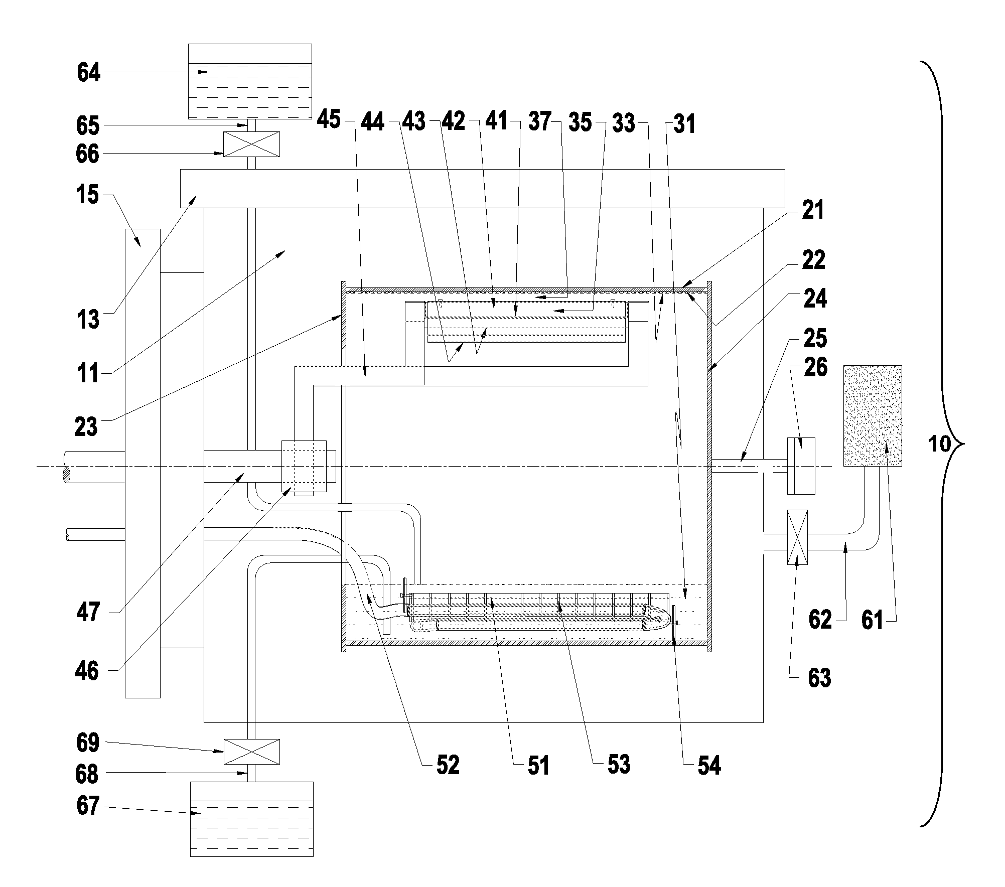
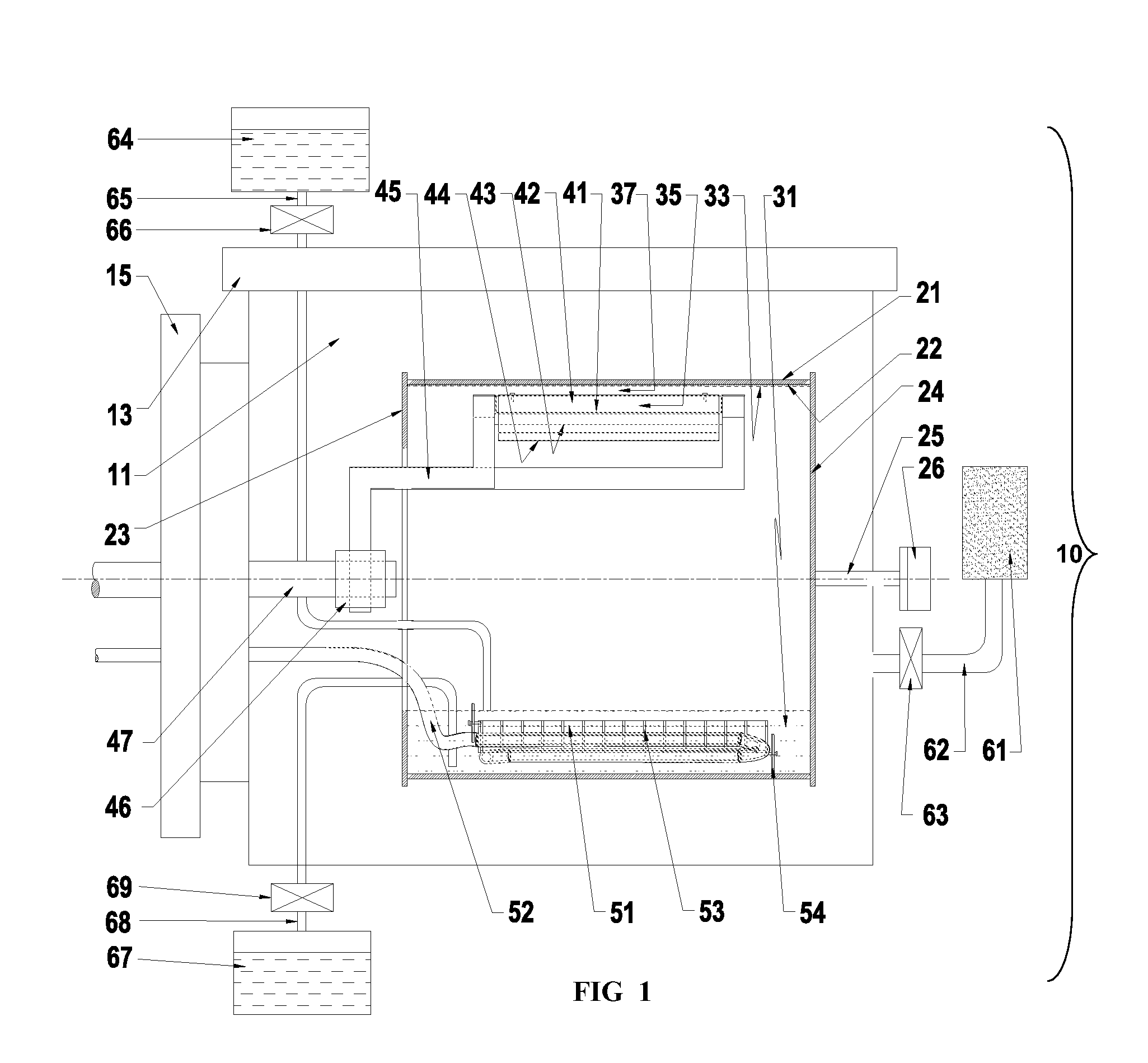
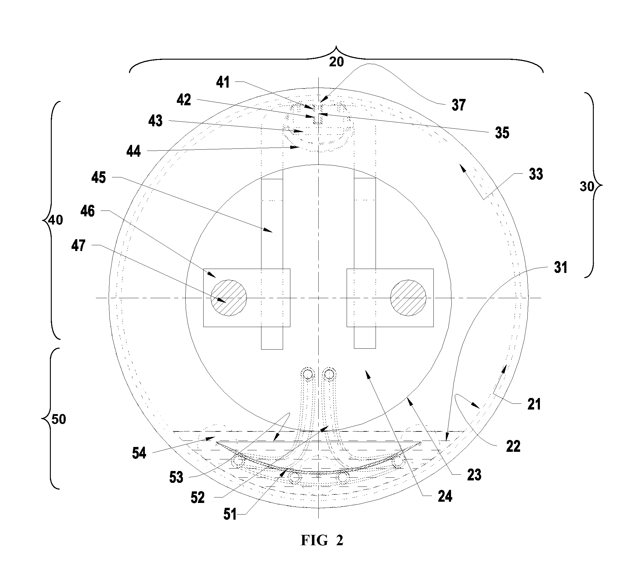
[0029]The most preferred embodiments of the invented one-step nanofluid production system 10 are presented in FIGS. 1-10. FIGS. 1, 2 and 3, illustrates one embodiment of the invented one-step nanofluid production system 10 using a rotating drum assembly 20, nanofluid material assembly 30, a heater boat-evaporator (HBE) assembly 40, and a heat-exchanger-cooler (HXC) assembly 50 in a vacuum chamber 11 along with optional innovative accessories group 60 (61-69), is shown. On FIGS. 2, 3 and 4 the most characteristic projections, orthogonal and isometric views of the rotating drum assembly 20 with nanofluid material assembly 30, including liquid pool 31 with thin film of liquid 33 and evaporant material 35, as well as the two critical assemblies, the heater-boat-evaporator (HBE) assembly 40 and heat-exchanger-cooler (HXC) assembly 50 are presented. The HBE assembly 40 is detailed on FIGS. 5 and 6, with the preferred functional positioning presented on FIG. 7, while the HXC assembly 50 is...


PUM

PropertyMeasurementUnit
sizeaaaaaaaaaa
sizeaaaaaaaaaa
sizeaaaaaaaaaa

Abstract

A one step method and system for producing nanofluids by a nanoparticle-source evaporation and deposition of the evaporant into a base fluid. The base fluid such oil or ethylene glycol is placed in a rotating cylindrical drum having an adjustable heater-boat-evaporator and heat exchanger-cooler apparatus. As the drum rotates, a thin liquid layer is formed on the inside surface of the drum. An insulated heater-boat-evaporator having an evaporant material (nanoparticle-source) placed within its boat evaporator is adjustably positioned near a portion of the rotating thin liquid layer, the evaporant material being heated thereby evaporating a portion of the evaporant material and forming nanoparticles, the nanoparticles absorbed by the liquid film to form nanofluid.

Description

RELATION TO PRIOR PATENT APPLICATIONS[0001]This application claims priority to, and is a divisional patent application of pending U.S. patent application Ser. No. 11 / 456,944, filed on Jul. 12, 2006, which is related to, and claims priority of, U.S. Provisional Patent Application No. 60 / 689,303 filed on Jul. 12, 2005, by instant inventors, all of which are hereby incorporated by reference in their entireties.[0002]STATEMENT OF GOVERNMENTAL SUPPORT[0003]The United States Government has certain rights in this invention pursuant to Contract No. W-31-109-ENG-38 between the U.S. Department of Energy and the University of Chicago operating Argonne National Laboratory.FIELD OF INVENTION[0004]The invention relates to a method and system for the manufacture of nanofluids. More particularly the invention relates to an improved one-step method and system for the manufacture of nanofluids.BACKGROUND OF THE INVENTION[0005]Nanotechnology is a rapidly developing science that is leading to numerous ...

Claims


Application Information

Patent Timeline
Patent Type & Authority Applications(United States)
IPC IPC(8): C09K5/00
CPCB01D1/223B01D1/228B01D1/28C09K5/10Y10S159/16Y10S977/70Y10S977/773Y10S977/84Y10S977/90
Inventor KOSTIC, MILIVOJEGOLUBOVIC, MIHAJLOHULL, JOHN R.CHOI, STEPHEN U.S.
Owner THE UNITED STATES AS REPRESENTED BY THE DEPARTMENT OF ENERGY
Why Eureka
Try Eureka