Projection type image display device

a projection type, image display technology, applied in the direction of optics, instruments, optical elements, etc., can solve the problems of short useful life, burdensome maintenance of light sources, and deterioration of image quality, so as to reduce speckle noise and less conspicuous pixels

Active Publication Date: 2010-07-08
PANASONIC CORP
View PDF10 Cites 34 Cited by
  • Summary
  • Abstract
  • Description
  • Claims
  • Application Information

AI Technical Summary

Benefits of technology

[0023]In accordance with the present invention, pixels are spatially separated into a plurality of pixels using a birefringence, so as to reduce the regions of the pixel grid that are the non-effective portion

Problems solved by technology

However, the use of a lamp as the light source is accompanied by a variety of problems, including: (1) short useful life and burdensome maintenance of the light source; (2) the complicated optical system required in order to separate white light into the three primary colors of light; and (3) a narrow color reproduction range.
However, due to the high coherency, use of laser light is associated with the problem of speckle noise generation that causes image quality deterioration.

Method used


Image

  • Projection type image display device
  • Projection type image display device
  • Projection type image display device

Examples


embodiment 1

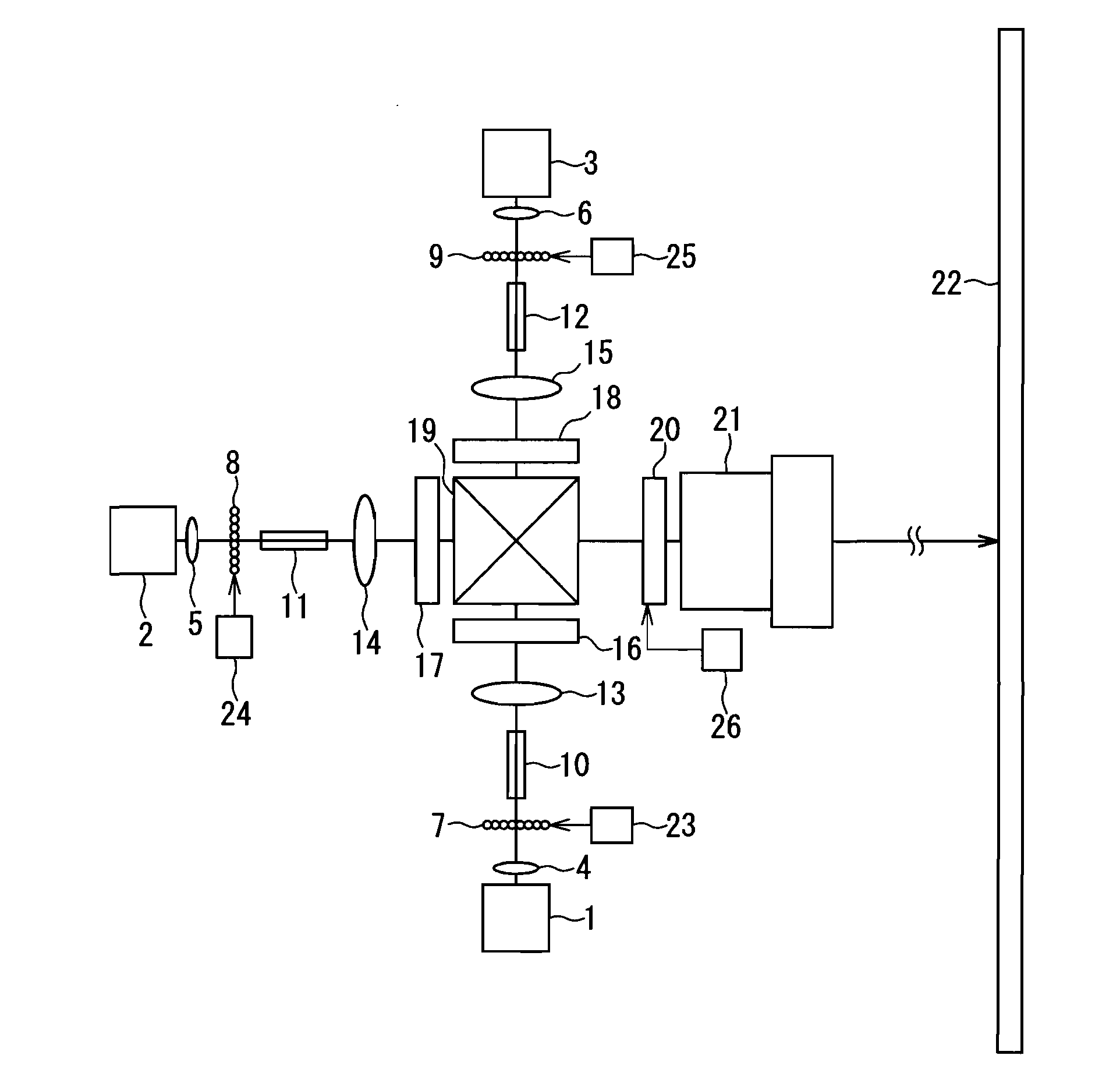
[0068]FIG. 1 is a diagram that describes a projection type image display device used in Embodiment 1 of the present invention. Three color laser light sources, i.e. red, green, and blue, are used in this embodiment. For example, a semiconductor laser that emits directly a laser light having a wavelength of 638 nm is used as a red laser light source 1, the second harmonic of an Yb fiber laser having a wavelength of 532 nm is used as a green laser light source 2, and a semiconductor laser that emits directly a laser light having a wavelength of 445 nm is used as a blue laser light source 3.

[0069]It should be obvious, however, that laser light sources suitable for carrying out the present invention are not limited to the laser light sources illustrated in this embodiment. For instance, the second harmonic of a near-infrared semiconductor laser can be used as the red laser light source 1. A semiconductor laser that lases directly in the green, the second harmonic of a near-infrared semi...

embodiment 2

[0097]FIG. 3 is a diagram that describes a projection type image display device used in Embodiment 2 of the present invention. This embodiment differs from Embodiment 1 in that a phase retardation plate 27 is added between the beam combining prism 19 and the birefringent plate 20. Accordingly, the same reference numerals are assigned to the same components as the components used in Embodiment 1, and the corresponding descriptions are omitted.

[0098]The phase retardation plate 27 is a quarter-wave plate that generates a phase difference of π / 2 between the S-polarization direction and the P-polarization direction. As it passes through the phase retardation plate 27, the polarization state of the red, green, and blue laser light is converted from linearly polarized light to circularly polarized light.

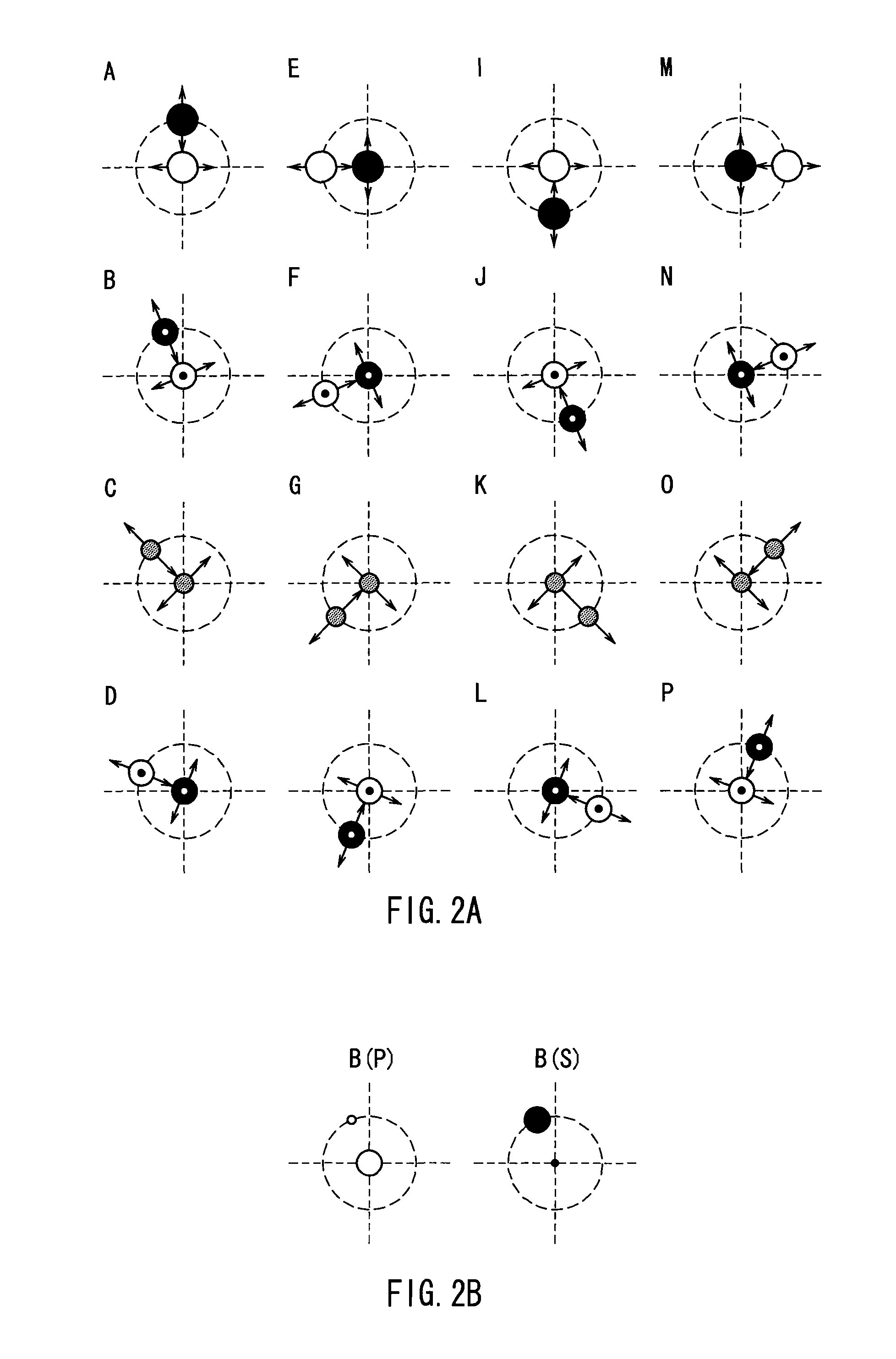
[0099]FIG. 4 shows a schematic illustration of the pixel patterns formed by light exiting from the birefringent plate 20 in the present embodiment. In the same manner as in FIG. 2, the 16 p...

embodiment 3

[0102]FIG. 5 is a diagram that describes a projection type image display device used in Embodiment 3 of the present invention. This embodiment differs from Embodiment 2 in that the birefringent plate 28, which constitutes a pixel separation element, is made up of three closely spaced first to third birefringent plates 28a-28c. The use of the first, second and third birefringent plates 28a-28c allows for spatially separating the pixel patterns into four pixels.

[0103]The arrangement of the birefringent plates used in this embodiment will be described in more detail below. The circularly polarized red, green, and blue light exiting from the phase retardation plate 27 impinges upon the first birefringent plate 28a, whereupon the light that exits from the first birefringent plate 28a impinges upon the second birefringent plate 28b and the light exiting from the second birefringent plate 28b impinges upon the third birefringent plate 28c. The optic axis of the second birefringent plate 28...


PUM


Abstract

Red, green, and blue laser light emitted from laser light sources 1-3 is transformed into substantially parallel beams by collimator lenses 4-6, collected by microlens arrays 7-9, and rendered uniform by rod integrators 10-12, whereupon it is used to illuminate spatial light modulation elements 16-18 and subjected to modulation. The modulated laser light exiting from the spatial light modulation elements 16-18 is recombined using a beam-combining prism 19 and subjected to pixel separation using a birefringent plate 20, which is rotationally driven by a birefringent plate rotary drive unit 26, after which it is projected upon a screen 22 using a projection optical system 21. The birefringent plate 20 spatially separates the modulated laser light using birefringence. When pixels are spatially separated by the birefringent plate, the pixel grid region is made smaller, the distribution of brightness on the screen is rendered uniform, and speckle noise is reduced.

Description

TECHNICAL FIELD [0001]The present invention relates to a projection type image display device, in which an image formed by spatial light modulation elements is illuminated with laser light and projected upon a screen using a projection lens.BACKGROUND ART [0002]Conventionally, projection type image display devices such as projectors have been used for obtaining large-screen images in an efficient manner. In projection type image display devices, liquid crystal panels or other spatial light modulation elements are used to form images in response to a picture signal and are illuminated with light from a lamp, so that their optical images are projected in an enlarged form upon a screen using a projection lens.[0003]However, the use of a lamp as the light source is accompanied by a variety of problems, including: (1) short useful life and burdensome maintenance of the light source; (2) the complicated optical system required in order to separate white light into the three primary colors...

Claims


Application Information

Patent Timeline
IPC IPC(8): G03B21/14G02B26/00G02F1/13
CPCG02B5/3083G02B26/06G02B27/48G03B33/12H04N9/3105H04N9/3161H04N9/3164G03B21/2033G03B21/208
Inventor KITANO, HIROSHIFUSHIMI, YOSHIMASA
Owner PANASONIC CORP
Why Eureka
Try Eureka