Apparatus and method for ocular treatment

a technology of ocular treatment and appendix, which is applied in the field of appendix and ocular treatment, can solve the problems of affecting the access to the eye for medical treatment, affecting the effect of ocular treatment, so as to facilitate tissue targeting and safe reach the posterior region.

Inactive Publication Date: 2010-07-08
ISCI INTERVENTIONAL CORP
View PDF107 Cites 197 Cited by
  • Summary
  • Abstract
  • Description
  • Claims
  • Application Information

AI Technical Summary

Benefits of technology

[0010]Whether curved or suitably flexible, the device should preferably have a minimum length in the range of about 20 to about 30 mm to safely reach the posterior region of the eye from an anterior dissection into the suprachoroidal space without damaging or causing undue distension of the choroid or other tissues.
[0011]The device may comprise an optical fiber for imaging tissues within or adjacent to the suprachoroidal space and an energy-emitting source for treating blood vessels within or adjacent to the suprachoroidal space. The source may be capable, for example, of emitting laser light, thermal energy, ultrasound, or electrical energy. Preferably the source is aligned with the location of the beacon to facilitate tissue targeting.

Problems solved by technology

Accessing the eye for medical treatment is hindered by the small size and delicate nature of the tissues.
In addition, the eye is immunologically privileged, rendering it susceptible to severe infection, especially when the intraocular space is challenged by both pathogens and trauma.
Dissection of the eye during surgery may affect the optical alignment of tissues involved in vision and typically results in scarring which makes subsequent surgery more difficult.

Method used


Image

  • Apparatus and method for ocular treatment
  • Apparatus and method for ocular treatment
  • Apparatus and method for ocular treatment

Examples


example 1

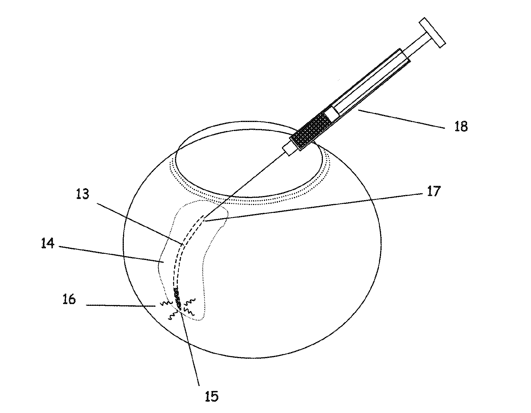
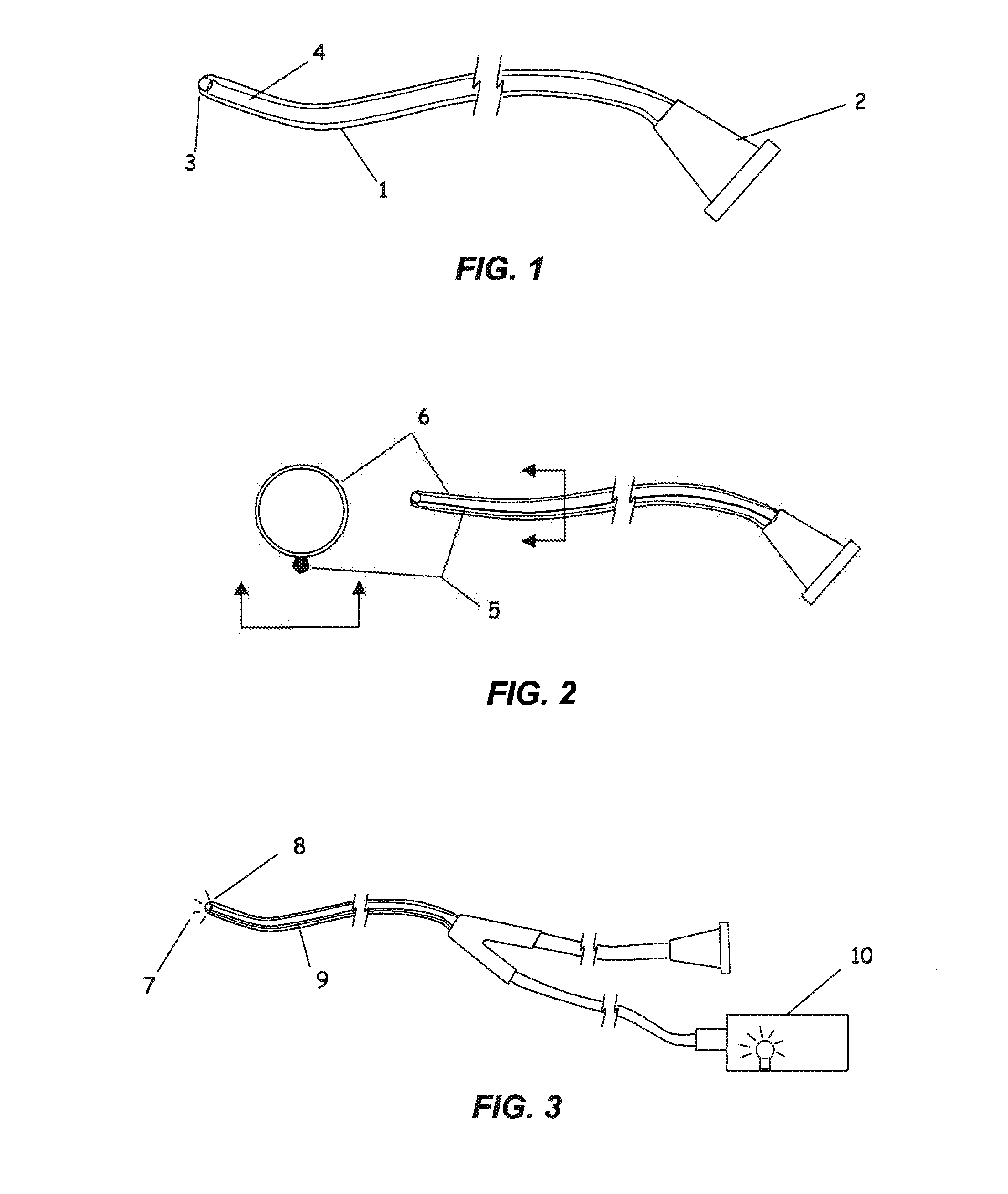
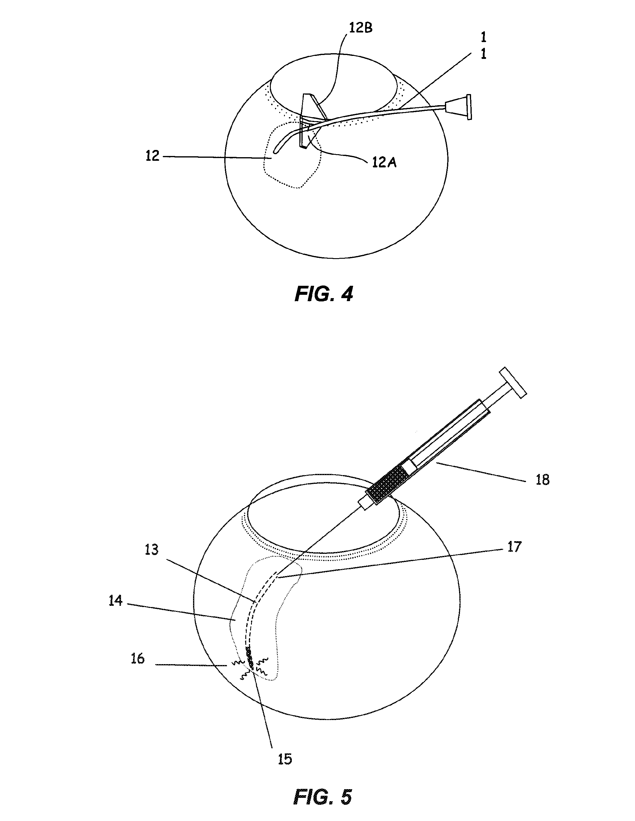
[0047]A flexible microcannula comprising a polyimide infusion lumen, a stainless steel anti-kink core wire and a plastic optical fiber to create a beacon signal at the device tip was fabricated. The components were bound together in a co-linear fashion using very thin walled heat shrink tubing of polyethylene terephthalate (PET). The assembled microcannula was approximately 300 microns in outer diameter, 75 microns inner diameter and with a working length of 25 mm. An atraumatic ball-shaped distal tip of approximately 370 microns diameter was produced by heating the end of the PET shrink tubing to its melt point prior to assembly. The surface tension of the melt results in the creation of a rounded ball-shaped tip. A fluoropolymer (Teflon) coated stainless steel wire was placed in the lumen to maintain the lumen during the melting of the tip. The proximal end of each microcannula consisted of an infusion tube connected proximally to a luer fitting and distally to the cannula shaft, ...

example 2

[0048]Two different sizes of flexible microcannulae comprising a polyether block amide (Pebax, Arkema Corp., Philadelphia Pa.) tubular shaft with an 85 micron diameter plastic optical fiber residing in the lumen to create a beacon signal at the device tip, were fabricated. The smaller microcannulae furthermore incorporated a stainless steel anti-kink core wire within the lumen and the shaft was fabricated using a 72D durometer shaft tube. The larger size of microcannula was fabricated from 63D durometer shaft tubing and furthermore incorporated markings at 5 mm intervals from 5 to 20 mm from the distal tip to aid in determining the depth of penetration during the initial placement into the suprachoroidal space. The distal tips of the tubes were formed into an atraumatic tip by applying heat to the distal end to allow the surface tension of the melt to form a ball shape. The distal 50 mm of each shaft was coated with a cross-linked polyvinylchloride based hydrophilic lubricious coati...

example 3

[0049]To determine the compliance range (flexural modulus) for flexible microcannula or catheter designs to access the suprachoroidal space (SCS) in a human eye, mechanical models were prepared with a range of stainless steel wire diameters to test a range of flexural rigidities. Furthermore, a 19 gauge stainless steel hypodermic tube was also tested. Flexural rigidity of a body is equal to the product of the flexural modulus, E, and the moment of inertia of the cross-section, I, and is typically called EI. The flexural rigidity of the microcannulae were evaluated by calculation for the tests units of uniform geometry and calculated and determined by mechanical testing for the prototype microcannulae. The microcannula cantilever force-displacement characteristics were tested on a mechanical testing apparatus with a high sensitivity load cell (Instron model 5542, 5N Load Cell). The linear region of the resultant data was used to calculate the measured flexural rigidity of the test sa...


PUM

PropertyMeasurementUnit
outer diameteraaaaaaaaaa
radiusaaaaaaaaaa
lengthaaaaaaaaaa

Abstract

The invention provides tools, materials and related methods to surgically access the suprachoroidal space of an eye for the purpose of performing minimally invasive surgery or to deliver drugs to the eye. The invention provides a flexible microcannula or microcatheter device (11, 13) that may be placed into the suprachoroidal space (12, 14) through a small incision (12A) of the overlying tissues, maneuvered into the appropriate region of the space, and then activated to treat tissues adjacent to the distal tip of the device.

Description

PRIORITY FROM RELATED APPLICATION[0001]This is a continuation-in-part of U.S. Ser. No. 11 / 587,784, filed Oct. 25, 2006. Priority is hereby claimed from U.S. Ser. No. 11 / 587,784, filed Oct. 25, 2006, which is a §371 application of PCT / US05 / 14980, filed Apr. 29, 2005, which in turn claims benefit of U.S. Provisional Application Ser. No. 60 / 566,776, filed Apr. 29, 2004, all of which are incorporated by reference herein in their entirety.BACKGROUND OF THE INVENTION[0002]The eye is a complex organ with a variety of specialized tissues that provide the optical and neurological processes for vision. Accessing the eye for medical treatment is hindered by the small size and delicate nature of the tissues. Surgical access must not affect the optical clarity or alignment of the tissues in the visual axis to preserve vision. In addition, the eye is immunologically privileged, rendering it susceptible to severe infection, especially when the intraocular space is challenged by both pathogens and ...

Claims


Application Information

Patent Timeline
Patent Type & Authority Applications(United States)
IPC IPC(8): A61K31/728A61M37/00A61F9/00A61F9/011A61B3/14A61K31/56A61P27/02
CPCA61B19/54A61B2019/5217A61B2019/5425A61B2019/5445A61F2009/00851A61F9/00736A61F9/00781A61F9/008A61F9/0017A61B2090/3945A61B2090/3614A61B90/39A61B2090/3925A61P27/02
Inventor HEE, MICHAELCONSTON, STANLEY R.KUPIECKI, DAVID J.MCKENZIE, JOHN R.YAMAMOTO, RONALDNASH, MICHAEL
Owner ISCI INTERVENTIONAL CORP
Why Eureka
Try Eureka