Apparatus and Method for Ocular Treatment

a technology of ocular treatment and appendix, which is applied in the field of appendix and ocular treatment, can solve the problems of difficult subsequent surgery, small size and delicate nature of the tissue, and impede the access to the eye for medical treatment,

Inactive Publication Date: 2008-03-06
ISCI INTERVENTIONAL CORP
View PDF14 Cites 249 Cited by
  • Summary
  • Abstract
  • Description
  • Claims
  • Application Information

AI Technical Summary

Benefits of technology

[0014] The device may comprise a signal-producing beacon to locate the distal end within the suprachoroidal space during implantation wherein the signal-producing beacon is detectable visually or by non-invasive imaging. The device may be adapted for slow release of fluids, such as drugs, from the distal end.

Problems solved by technology

Accessing the eye for medical treatment is hindered by the small size and delicate nature of the tissues.
In addition, the eye is immunologically privileged, rendering it susceptible to severe infection, especially when the intraocular space is challenged by both pathogens and trauma.
Dissection of the eye during surgery may affect the optical alignment of tissues involved in vision and typically results in scarring which makes subsequent surgery more difficult.

Method used


Image

  • Apparatus and Method for Ocular Treatment
  • Apparatus and Method for Ocular Treatment
  • Apparatus and Method for Ocular Treatment

Examples


example 1

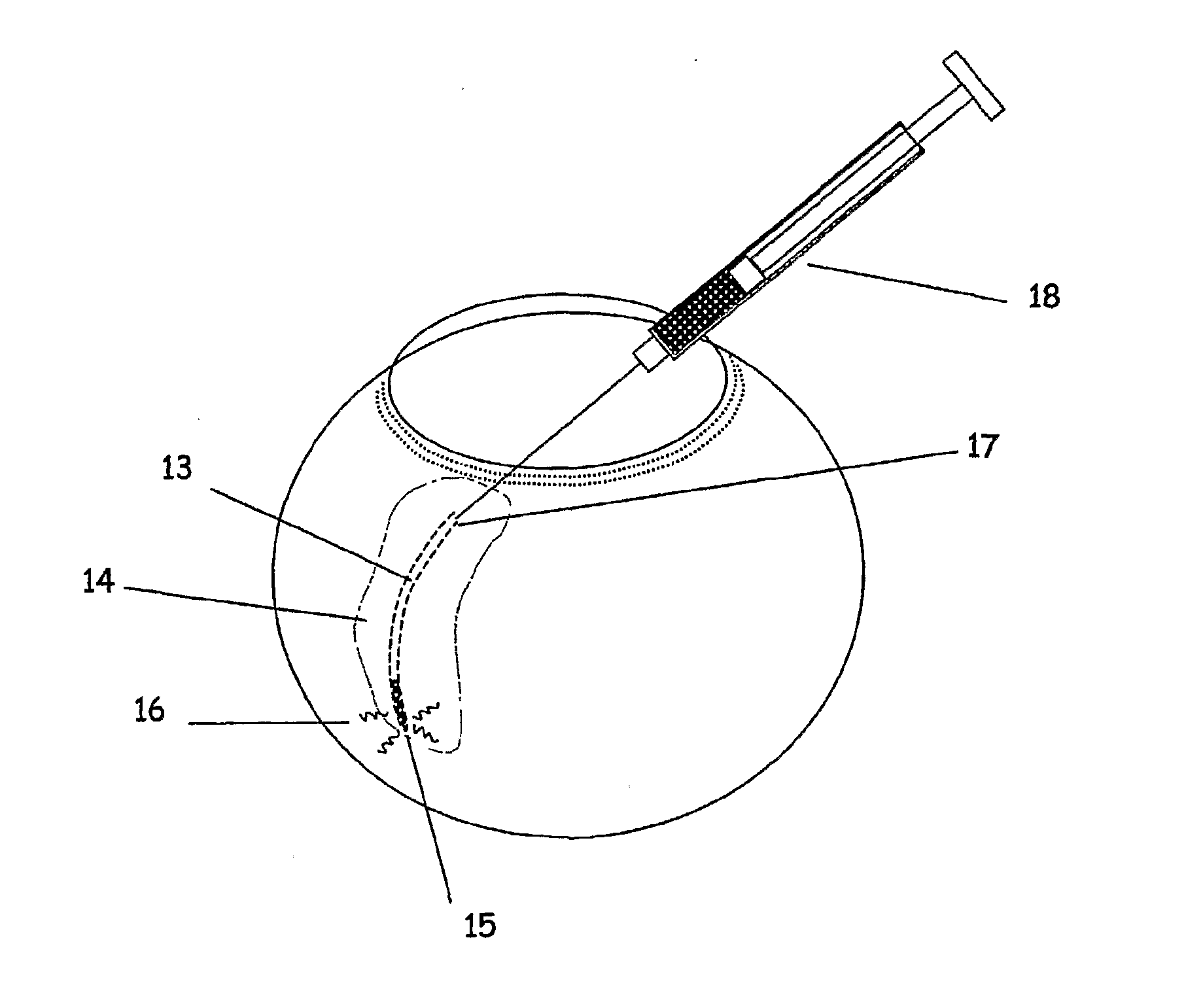
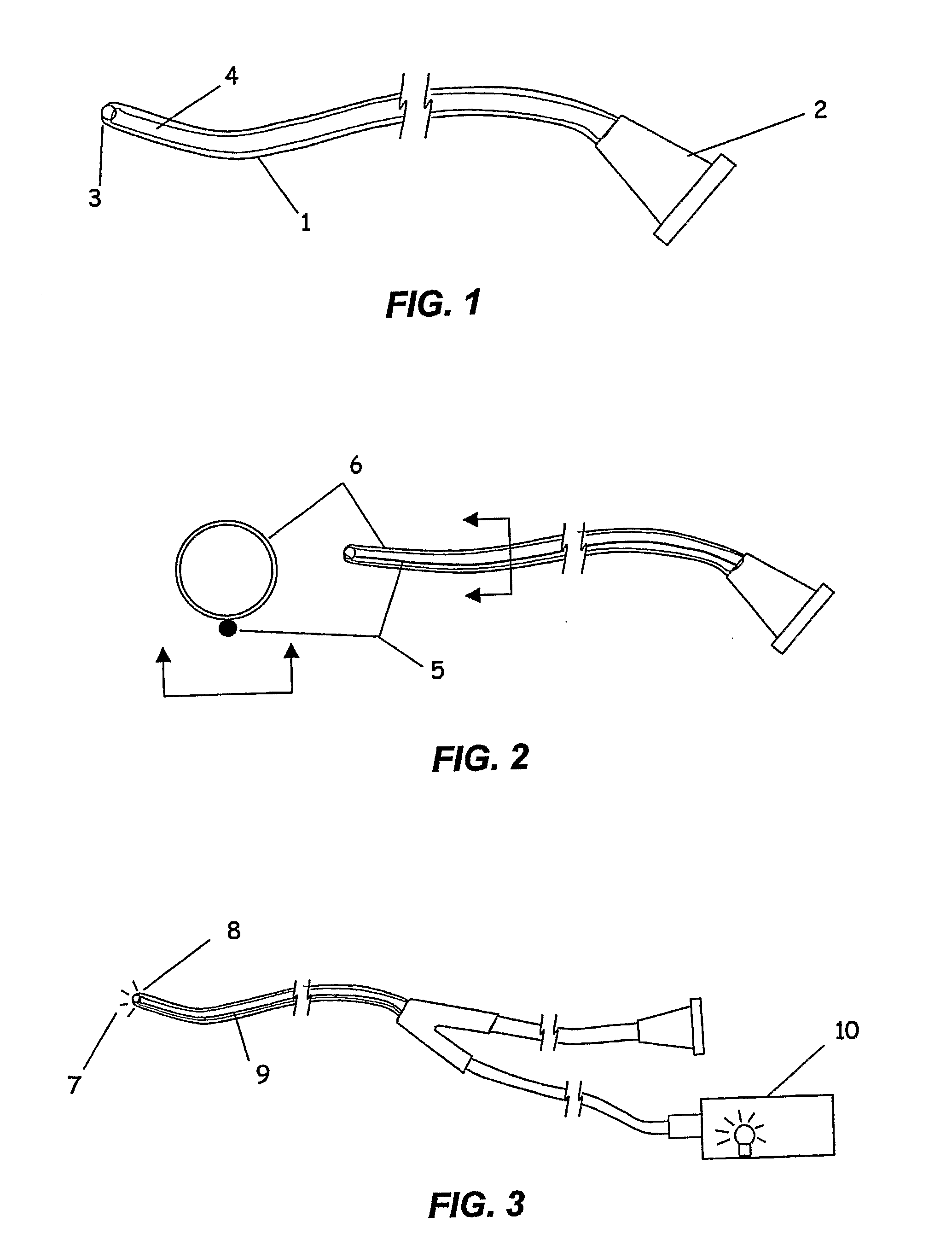
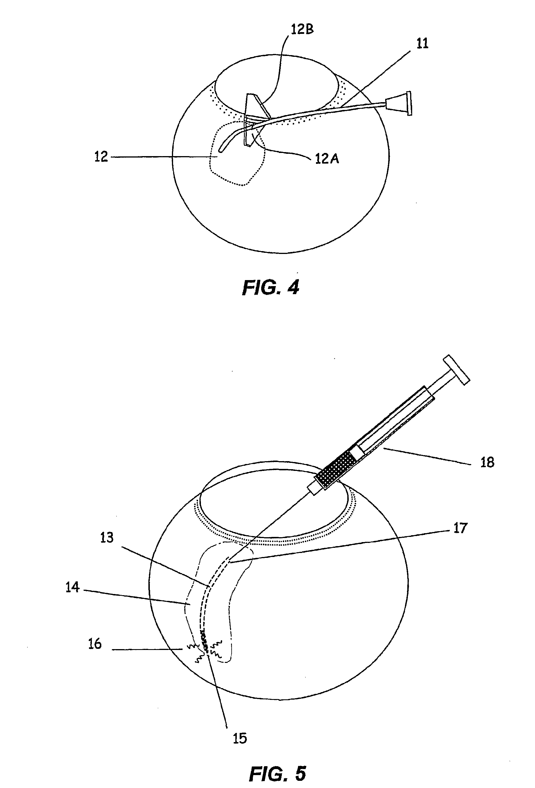
[0057] A microcannula comprising a polyimide infusion lumen, a stainless steel anti-kink core wire and a plastic optical fiber to create a beacon signal at the device tip was fabricated. The components were bound together using very thin walled heat shrink tubing of polyethylene terephthalate (PET). The assembled microcannula was approximately 200 microns in outer diameter, 75 microns inner diameter and with a working length of 25 mm. An atraumatic ball-shaped distal tip was produced by heating the end of the PET shrink tubing to it's melt point prior to assembly. The surface tension of the melt results in the creation of a rounded ball-shaped tip. A stainless steel wire was placed in the lumen to maintain the lumen during the melting of the tip. The proximal end consisted of an infusion tube connected to a luer fitting, and a fiber optic light pipe connected to a 25 mW laser diode illumination source. The luer fitting was attached to an injector filled with a surgical viscoelastic ...

example 2

[0059] A drug formulation was prepared for suprachoroidal administration by injection through a microcannula of the present invention. Three milliliters of sterile triamcinolone acetonide suspension (Kenalog 40, 40 mg / ml, Bristol Meyers Squib) was withdrawn into a sterile syringe. The syringe was attached to a sterile 0.45 micron syringe filter and the drug suspension was injected into the filter, capturing the drug particles. A second syringe with an adjunct mixer was attached to the filter and 0.6 milliliters of sterile hyaluronic acid solution (Healon, 10 mg / ml, Advanced Medical Optics, Irvine, Calif.) introduced into the filter containing the drug particles. The hyaluronic acid and drug particles were then withdrawn into the first syringe and the filter removed. The hyaluronic acid and drug particles were mixed by multiple passage between two sterile syringes. The suspended drug formulation contained 200 mg / ml triamcinolone acetonide and 10 mg / ml hyaluronic acid. The drug formul...

example 3

[0060] Microcannulae were fabricated, comprising a communicating element of 65 Shore D durometer Pebax tubing of 0.008″×0.0010″ diameter, containing a plastic optical fiber 0.0033″ diameter and a stainless steel wire 0.001″ diameter within the lumen. The plastic optical fiber was connected to a laser diode light source similar to that used in Example 1 to provide for an illuminated beacon distal tip. The steel wire was incorporated to prevent kinking of the shaft. The lumen of the tube was attached to a larger plastic tube and then to a proximal Luer connector for the attachment of a syringe or viscoelastic injector. An atraumatic distal tip was created by applying a small amount of high viscosity ultraviolet cure adhesive and allowing the surface tension to create a ball-shaped tip prior to curing. The devices were sterilized for use by gamma irradiation.

[0061] Animal studies were performed to evaluate the microcannula in accessing the suprachoroidal space and advancing to the pos...


PUM


Abstract

The invention provides tools, materials and related methods to surgically access the suprachoroidal space of an eye for the purpose of performing minimally invasive surgery or to deliver drugs to the eye. The invention provides a flexible microcannula device (11, 13) that may be placed into the suprachoroidal space (12, 14) through a small incision (12A) of the overlying tissues, maneuvered into the appropriate region of the space, and then activated to treat tissues adjacent to the distal tip of the device.

Description

PRIORITY FROM RELATED APPLICATION [0001] Priority is hereby claimed from U.S. Provisional Application Ser. No. 60 / 566,776, filed Apr. 29, 2004, which is incorporated by reference herein in its entirety.BACKGROUND OF THE INVENTION [0002] The eye is a complex organ with a variety of specialized tissues that provide the optical and neurological processes for vision. Accessing the eye for medical treatment is hindered by the small size and delicate nature of the tissues. Surgical access must not affect the optical clarity or alignment of the tissues in the visual axis to preserve vision. In addition, the eye is immunologically privileged, rendering it susceptible to severe infection, especially when the intraocular space is challenged by both pathogens and trauma. [0003] Minimally invasive surgical methods to access and treat tissues of the eye are desired to minimize trauma and introduction of pathogens. Dissection of the eye during surgery may affect the optical alignment of tissues i...

Claims


Application Information

Patent Timeline
Patent Type & Authority Applications(United States)
IPC IPC(8): A61F9/00A61M31/00
CPCA61B19/54A61B2019/5217A61F9/0017A61F9/00736A61F9/00781A61F2009/00887A61F9/009A61F2009/00863A61F2009/00865A61F2009/00872A61F9/008A61B90/39A61B2090/3614
Inventor HEE, MICHAELCONSTON, STANLEY R.KUPIECKI, DAVID J.MCKENZIE, JOHN R.YAMAMOTO, RONALDNASH, MICHAEL
Owner ISCI INTERVENTIONAL CORP
Why Eureka
Try Eureka