Thermal modeling of an orthogonal machining process

a technology of thermomechanical analysis and orthogonal machining, applied in the direction of analogue processes, cad techniques, instruments, etc., can solve the problems of not reaching steady state for reasonable termination times, computationally expensive, and inability to obtain steady state temperature distribution, etc., to achieve specific heat of the tool, reduce the effect of thermal inertia per unit volum

Active Publication Date: 2010-07-08
MADHAVAN VISWANATHAN +1
View PDF8 Cites 30 Cited by
  • Summary
  • Abstract
  • Description
  • Claims
  • Application Information

AI Technical Summary

Benefits of technology

[0018]Obtaining steady state temperature distribution is computationally very expensive, either via a single coupled thermomechanical analysis, or via a multi-step iterative sequence of thermomechanical and steady state analyses. Transient FEA results show that the time constant of the temperature changes of the tool is very high, causing the temperature to not reach steady state for reasonable termination times in coupled thermomechanical analyses. Our invention involves reducing the thermal inertia per unit volume (specific heat capacity) of the cutting tool by scaling down the specific heat of the tool by a large factor and carrying out a short duration single step thermomechanical analysis to attain the steady state temperature distribution. It is shown that the thermal time constant for regions of scaled specific heat capacity is reduced by the same scaling factor used for the specific heat capacity, thus attaining a steady state temperature distribution very rapidly. Based on sound theoretical principles, it is shown that the steady state temperature distribution achieved by scaling the specific heat capacity is fully accurate, ...

Problems solved by technology

Obtaining steady state temperature distribution is computationally very expensive, either via a single coupled thermomechanical analysis, or via a multi-step iterative sequence of thermomechanical and steady state analys...

Method used


Image

  • Thermal modeling of an orthogonal machining process
  • Thermal modeling of an orthogonal machining process
  • Thermal modeling of an orthogonal machining process

Examples


Embodiment Construction

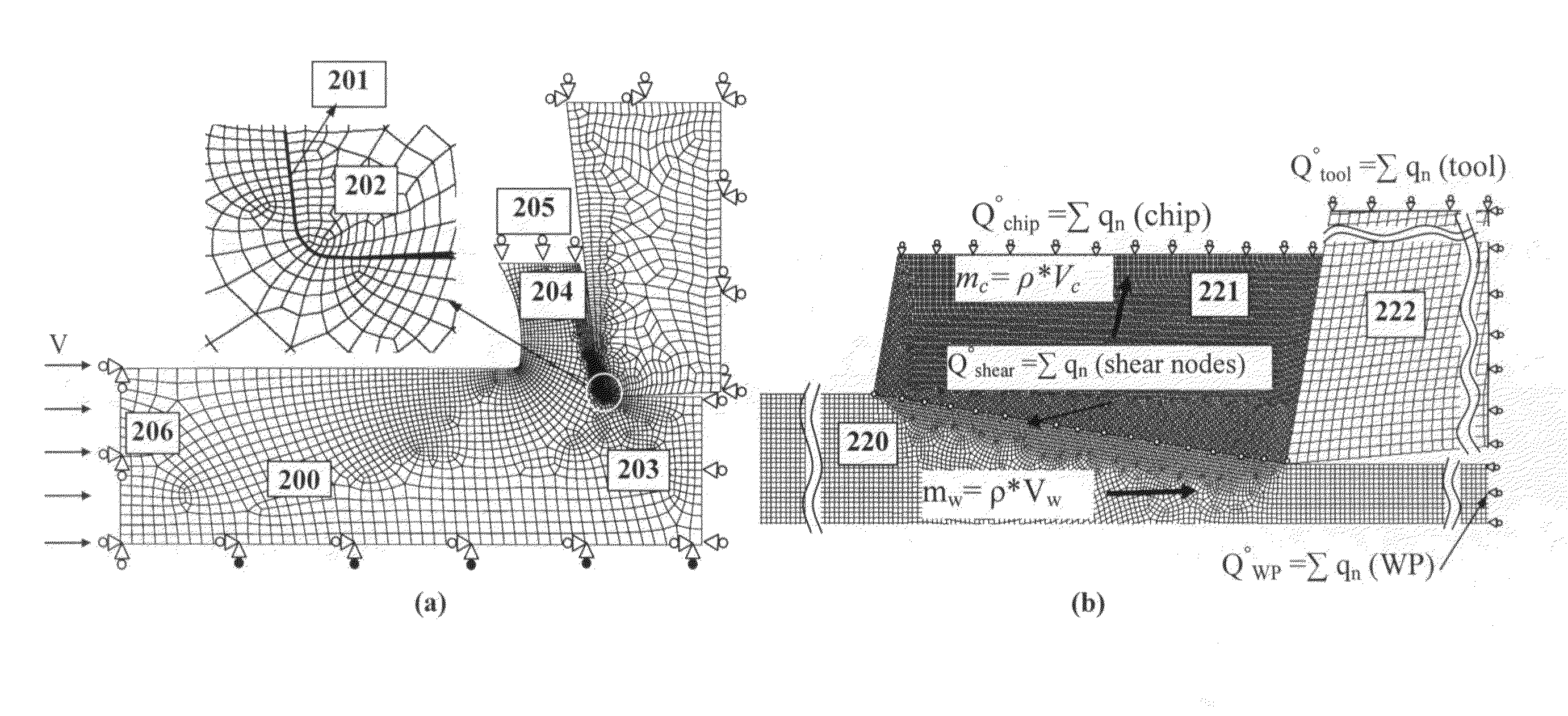
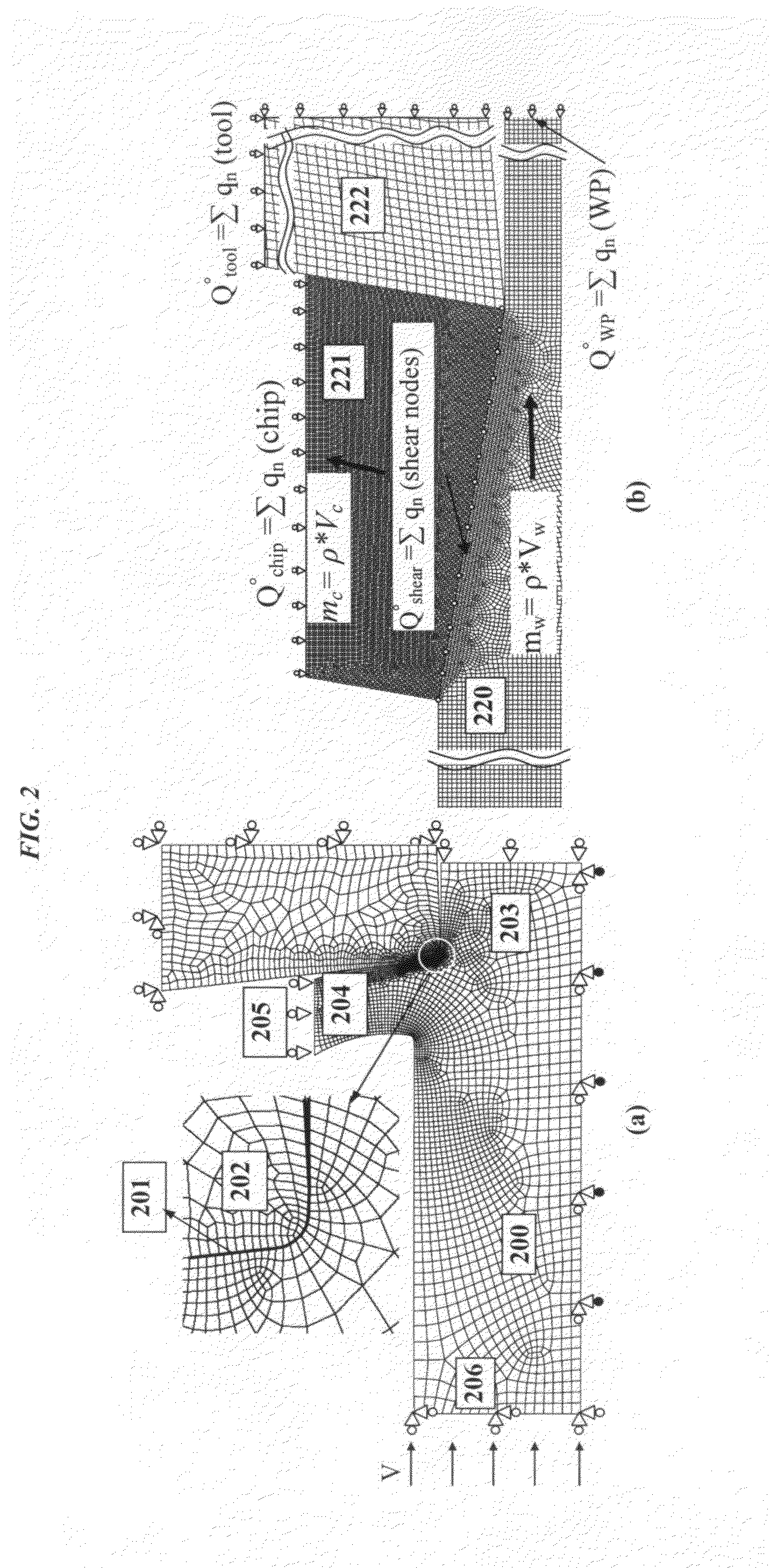
[0032]In the following we illustrate the invention using machining (also known as cutting) as a specific embodiment of the way in which the invention may be practiced. This embodiment is described in sufficient detail to enable those skilled in the art to practice the invention. It is to be understood that other embodiments may be utilized and that structural, logical and practical changes may be made without departing from the scope of the present invention. The scope of the present invention is defined by the appended claims and therefore the following description of example embodiments should not to be taken in a limited sense.

[0033]The present subject matter concerns the thermal modeling of a metal cutting process. Various embodiments model the thermal properties of a tool for machining. The present subject matter extends to metallic tools, as well as those that are not. Further, the present subject matter extends to workpieces that are metallic, as well as those that are not.

[0...


PUM


Abstract

A novel procedure is disclosed, that can be incorporated into Finite Element Analysis (FEA) or other similar analysis techniques, to obtain the steady state temperature distribution in a coupled transient heat transfer analysis rapidly as well as accurately. A scale factor is used to reduce the thermal inertia per unit volume (specific heat capacity) in regions of steady state temperature distribution, thereby hastening the achievement of steady state. An application of this procedure to estimate steady state temperature distributions within cutting tools, and the estimation of cutting tool wear based on the obtained steady state temperature distributions is shown as an example.

Description

CROSS-REFERENCE TO RELATED APPLICATIONS[0001]The present patent application claims benefit and priority to U.S. Prov. Pat. Appl. No. 61 / 139,321 (EFS ID 4495067) entitled “Thermal modeling of an orthogonal machining process” and filed on Dec. 19, 2008 which is hereby incorporated by reference into the present disclosure.BACKGROUND OF THE INVENTION[0002]1. Technical Field[0003]The subject matter includes a procedure that can be incorporated into Finite Element Analysis (FEA) or other similar analysis techniques, to obtain the steady state temperature distribution in a coupled transient heat transfer analysis rapidly as well as accurately.[0004]2. Background Art[0005]In 1971 Tay and Stevenson made use of the finite element method for evaluation of the temperature distribution along the chip tool interface. They carried out a heat transfer analysis with the actual geometry and size of the chip, workpiece and tool. The heat sources in both the primary and the secondary shear zone were ca...

Claims


Application Information

Patent Timeline
IPC IPC(8): G06F17/11G06F17/50
CPCG06F17/5018G06F2217/80G06F2217/16G06F30/23G06F2111/10G06F2119/08
Inventor MADHAVAN, VISWANATHANDESHPANDE, AMIT
Owner MADHAVAN VISWANATHAN
Why Eureka
Try Eureka